
Laser-induced transfer micro electronic component printing method based on non-Newtonian fluid characteristics

A non-Newtonian fluid, laser-induced technology, applied in the direction of process efficiency improvement, energy efficiency improvement, additive manufacturing, etc., can solve the problems of large structure size of deposited material, nozzle blockage, and low accuracy of deposited material delivery.

Pending Publication Date: 2022-03-15
GUANGDONG UNIV OF TECH
View PDF9 Cites 0 Cited by
  • Summary
  • Abstract
  • Description
  • Claims
  • Application Information

AI Technical Summary

Problems solved by technology

[0007] The purpose of the present invention is to solve the problems of nozzle clogging and larger structure size of deposits existing in existing ink direct writing and inkjet printing technologies, and the problems that most deposits are ablated by laser and transmission accuracy is not high in traditional laser direct writing technology , providing a laser-induced transfer microelectronic component printing method based on the characteristics of non-Newtonian fluids

Method used


Image

  • Laser-induced transfer micro electronic component printing method based on non-Newtonian fluid characteristics
  • Laser-induced transfer micro electronic component printing method based on non-Newtonian fluid characteristics

Examples


Embodiment

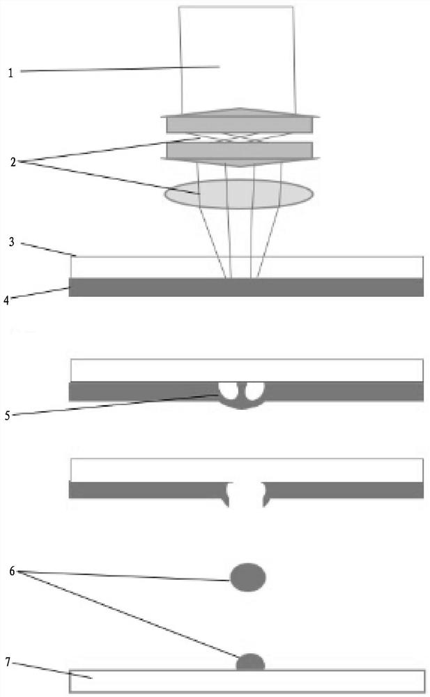
[0025] see figure 1 and figure 2 , this embodiment relates to a laser-induced transfer microelectronic component printing method based on non-Newtonian fluid characteristics, comprising the following steps:

[0026] Include the following steps:

[0027] Step 1. The pulsed laser beam 1 is incident on the combination lens, and the ring beam is formed after being shaped by the combination lens 2; the ring beam passes through the transparent cover plate 3 and focuses on the non-Newtonian fluid doped metal nanoparticle solution 4 to form a ring spot; During the process, the size of the inner and outer diameters of the annular light spot can be changed by adjusting the relative position between the lens of the combination lens 2 and the transparent cover plate 3;

[0028] Step 2, the nano-metal particles are ablated under the light and heat of the laser and form a plasma annular cavitation bubble 5;

[0029] Step 3, the ring-shaped cavitation bubble 5 rapidly expands and pushes ...


PUM


Abstract

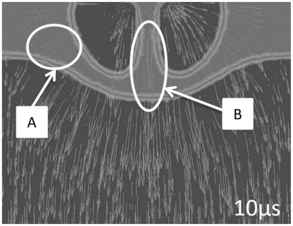
The invention discloses a laser-induced transfer micro electronic component printing method based on non-Newtonian fluid characteristics. The laser-induced transfer micro electronic component printing method comprises the steps that S1, emergent light focuses on a nano metal solution to form an annular light spot; s2, the metal particles form plasma annular cavitation bubbles under the action of laser; s3, rapidly expanding the annular cavitation bubbles, and simultaneously pushing the annular center target transfer object downwards; s4, high pressure generated by cavitation bubble expansion and high-speed impact of the laser act on the non-Newtonian fluid doped nano-metal particle solution at the same time; molecules in the non-Newtonian fluid doped nano-metal particle solution are mutually locked, rapidly shrink, tighten and harden, and absorb and digest external force, so that a target transfer object is stripped from the inside of the solution; and S5, the target transfer object is deposited on the receiving plate under the action of the gravity and kinetic energy of the target transfer object. Nozzles and masks are not needed, so that the nozzles cannot be blocked, the deposition efficiency is improved, and the process is simplified.

Description

technical field [0001] The invention relates to a method for printing microelectronic components, in particular to a method for printing microelectronic components based on the characteristics of non-Newtonian fluid induced by laser transfer. Background technique [0002] Direct writing technology is a micro-fabrication technology that constructs structural and functional units on a substrate through micro-regional reactions or material transfer. Ink direct writing, inkjet printing and laser direct writing are the most common direct writing technologies, which have powerful two-dimensional and three-dimensional forming capabilities and are widely used in electronic connecting wires, micro-batteries, micro-electrodes, photonic crystals and tissue engineering scaffolds. [0003] Ink direct writing technology is to store the metal nano-ink material in the barrel and the nozzle and install it on the three-axis control platform. Through the screw extrusion or pneumatic pressure c...

Claims


Application Information

Patent Timeline
Patent Type & Authority Applications(China)
IPC IPC(8): B22F10/28B22F10/64B22F10/85B33Y10/00B33Y50/02
CPCB22F10/28B22F10/64B22F10/85B33Y10/00B33Y50/02Y02P10/25
Inventor 邓宇谢凯武林士楠章宇健张璆蔡俊劲钟世裕
Owner GUANGDONG UNIV OF TECH
Learn More