Microwave plasma torch device with double microwave resonant cavities and use method of microwave plasma torch device
A microwave plasma and microwave resonant cavity technology, applied in the field of analysis, can solve the problems of low microwave-plasma coupling efficiency, large volume of MPT electromagnetic shielding cover, reducing microwave radiation, etc., and achieves wide applicable power range, strong excitation ability, Reduce the effect of microwave radiation
- Summary
- Abstract
- Description
- Claims
- Application Information
AI Technical Summary
Problems solved by technology
Method used
Image
Examples
specific Embodiment 1
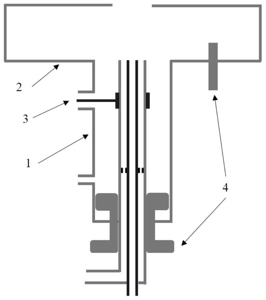
[0039] Specific embodiment 1 provides the microwave plasma torch device of the patent of the present invention, and combines figure 1 A schematic diagram of a typical structure is given.
[0040] The microwave plasma torch device is composed of a cavity part, a microwave coupling part and a tuning part;
[0041] The cavity part includes a resonant cavity 1 and a resonant cavity 2 placed coaxially, and the resonant cavity 2 is placed on the resonant cavity 1;
[0042] Resonant cavity 1 is a three-tube coaxial resonant cavity structure with one end open, the outer tube and the middle tube are made of metal, and the microwave transmission mode between the outer tube and the middle tube is TEM mode; the material of the inner tube can be metal or It can be non-metal, and when it is metal, the microwave transmission mode between the middle tube and the inner tube is also TEM mode; the inner tube can also be a cylindrical structure. Gas can be introduced into the three pipes, prefe...
specific Embodiment 2
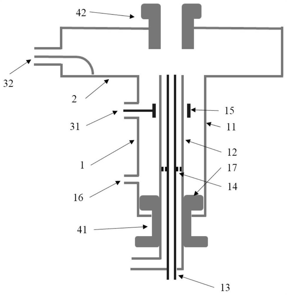
[0063] figure 2 Another structural schematic diagram according to the patent of the present invention is given.
[0064] The microwave plasma torch device is composed of a cavity part, a microwave coupling part and a tuning part;
[0065] The cavity part includes a resonant cavity 1 and a resonant cavity 2 placed coaxially, and the resonant cavity 2 is placed on the resonant cavity 1;
[0066] The resonant cavity-1 is composed of an outer tube 11, a middle tube 12, an inner tube 13, a porous concentric gasket 14, a coupling ring 15, a tangential inflow port 16, and a reflective end face 17;
[0067] The outer tube, the middle tube, and the inner tube are coaxially placed, and the upper end surfaces of the three tubes are flush with the upper surface of the second lower cover plate of the resonance cavity;
[0068] The porous concentric gasket 14 is made of metal, and the distance from the upper port of the middle tube is about 1 / 4 wavelength odd times, and forms an inner co...
specific Embodiment 3
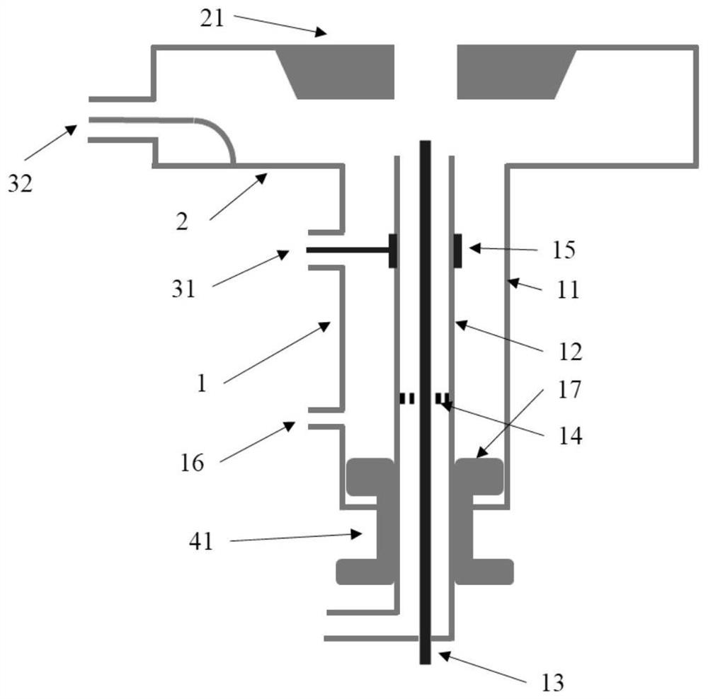
[0074] image 3 Another structural schematic diagram according to the patent of the present invention is given.
[0075] The microwave plasma torch device is composed of a cavity part, a microwave coupling part and a tuning part;
[0076] and figure 2 The differences are:
[0077] The inner tube 13 is a solid cylindrical metal conductor;
[0078] The upper end surface of the middle pipe is higher than the upper end surface of the outer pipe, and the upper end surface of the inner pipe is higher than the upper end surface of the middle pipe;
[0079] The porous concentric gasket 14 is made of metal, and the distance from the upper port of the middle pipe is an odd multiple of 1 / 4 wavelength, forming an inner coaxial resonant cavity structure with the middle pipe and the inner pipe;
[0080] The resonant cavity two 2 is a reentrant TM 010 Resonant cavity structure, the lower surface of the upper cover plate is a flat-topped conical boss 21 with a hollow structure, and its ...
PUM
 Abstract
Description
Claims
Application Information
 - R&D
- Intellectual Property
- Life Sciences
- Materials
- Tech Scout
- Unparalleled Data Quality
- Higher Quality Content
- 60% Fewer Hallucinations
Browse by: Latest US Patents, China's latest patents, Technical Efficacy Thesaurus, Application Domain, Technology Topic, Popular Technical Reports.
© 2025 PatSnap. All rights reserved.Legal|Privacy policy|Modern Slavery Act Transparency Statement|Sitemap|About US| Contact US: help@patsnap.com


