A Microwave Coupled Plasma Resonator
A technology of coupling plasma and resonant cavity, applied in the direction of plasma, ion source/gun, particle separation tube, etc. Unstable state and other problems, to achieve high microwave energy utilization, perfect unity of power density and volume, and a wide range of applications
- Summary
- Abstract
- Description
- Claims
- Application Information
AI Technical Summary
Problems solved by technology
Method used
Image
Examples
Embodiment 1
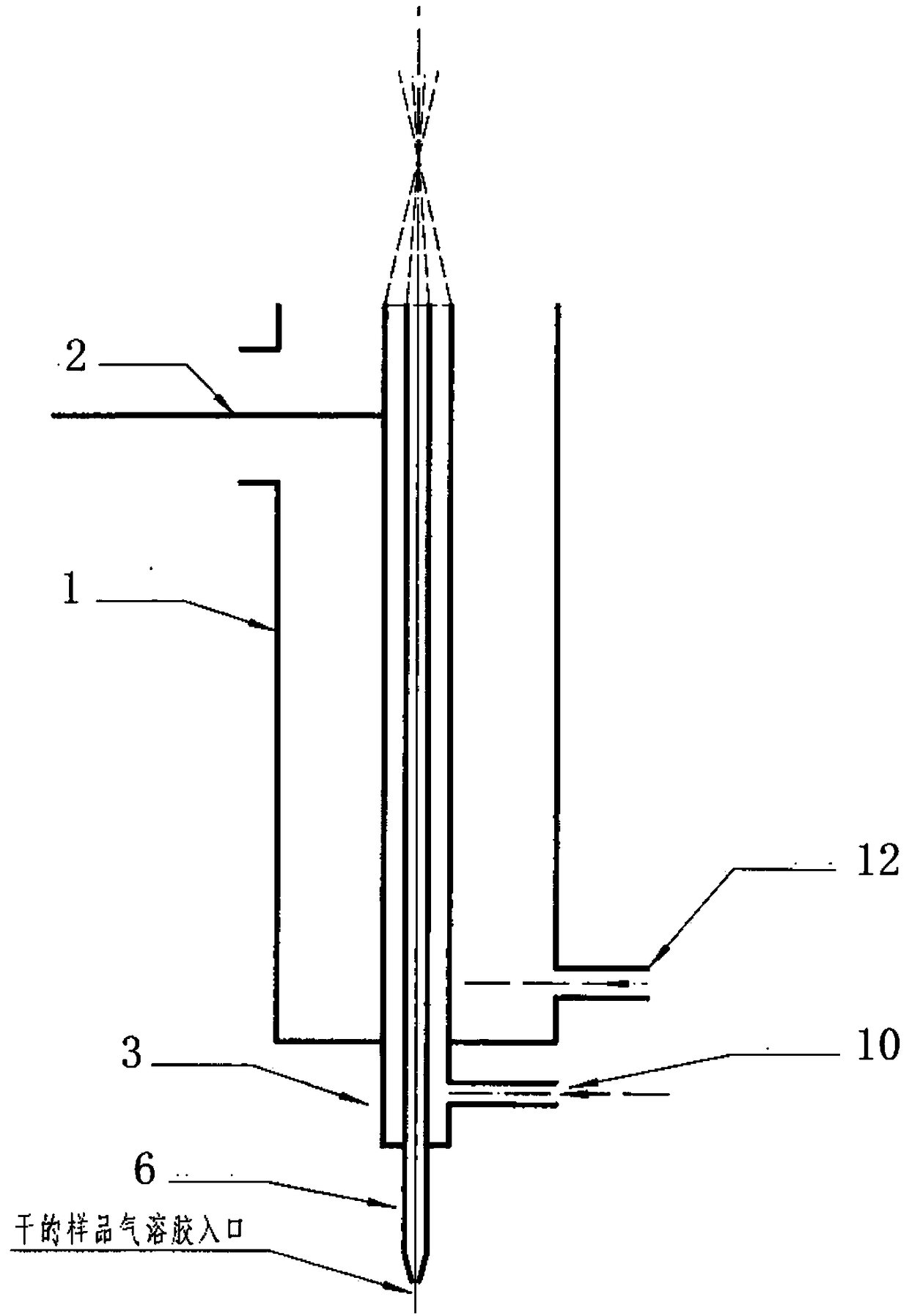
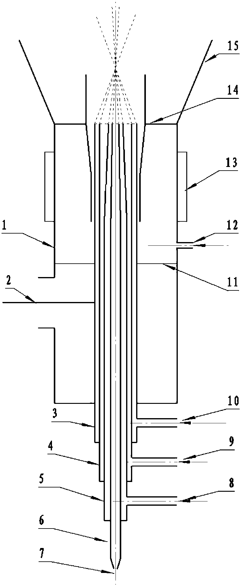
[0035] like figure 2 As shown, it is a microwave resonant cavity capable of generating triple compound laminar microwave-coupled plasma (MCP). The structure includes an outer conductor 1, a microwave antenna 2, an inner conductor 3, a middle tube 4, an inner tube 5, a sample tube 6, Sample inlet 7, auxiliary gas inlet 8, working gas inlet 9, maintenance gas inlet 10, shielding gas partition 11, shielding gas inlet 12, cooling ring 13, shielding gas choke cone 14 and impedance matching cone 15.
[0036] The resonant cavity provided in this embodiment is sequentially designed with hollow outer conductor 1 , inner conductor 3 , middle tube 4 , inner tube 5 , and sample tube 6 with coincident axes from outside to inside. Wherein, the inner conductor 3 is designed inside the outer conductor 1 , the middle tube 4 is designed inside the inner conductor 3 , the inner tube 5 is designed inside the middle tube 4 , and the sample tube 6 is designed inside the inner tube 5 . The sample ...
Embodiment 2
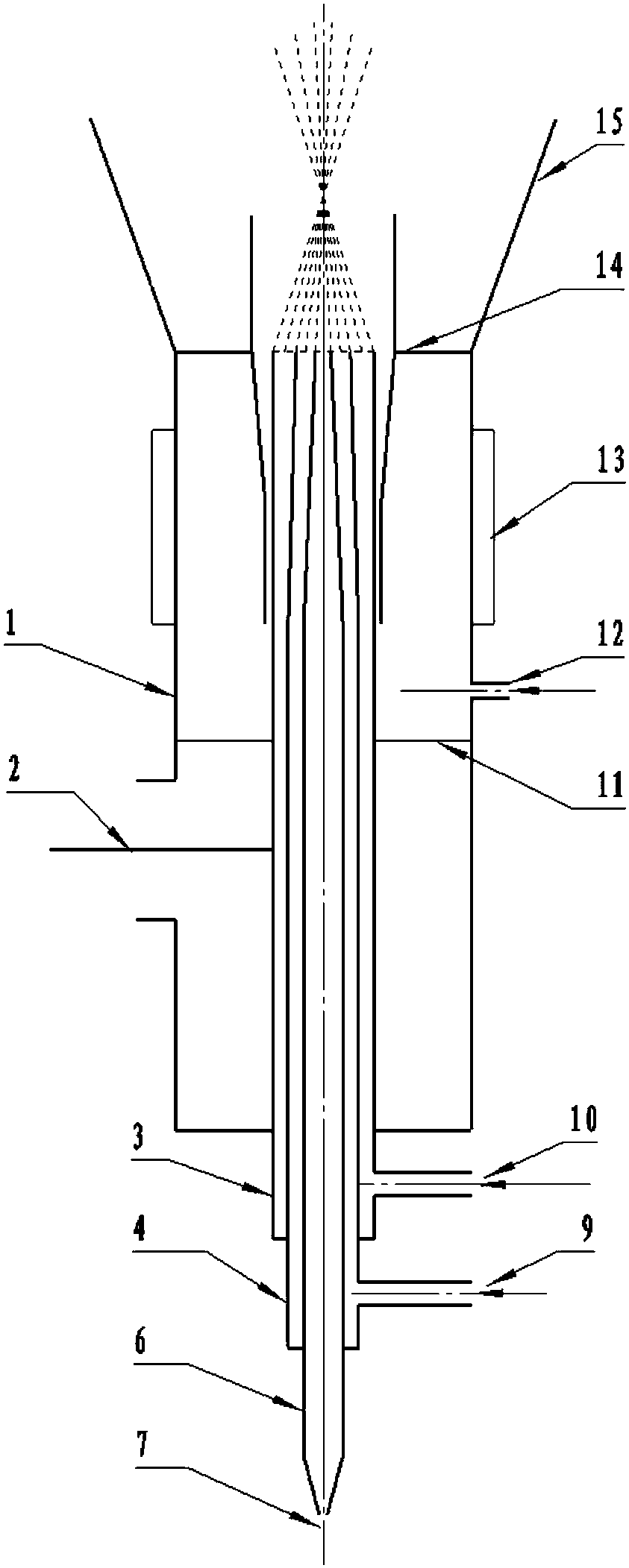
[0068] like image 3 As shown, it is a microwave resonant cavity capable of generating double compound laminar microwave coupled plasma (MCP), and its structure includes an outer conductor 1, a microwave antenna 2, an inner conductor 3, a middle tube 4, a sample tube 6, a sample inlet 7, Working gas inlet 9 , maintenance gas inlet 10 , shielding gas partition 11 , shielding gas inlet 12 , cooling ring 13 , shielding gas choke cone 14 and impedance matching cone 15 .
[0069] Compared with Embodiment 1, this embodiment differs in that the inner tube 5 and the auxiliary gas inlet 8 are missing, the inner diameter of the outer conductor 1 is 26-56 mm, the outer diameter of the inner conductor 3 is preferably 8-16 mm, and the inner diameter is preferably 6-14 mm. The microwave source used in the microwave resonant cavity of this embodiment is the same as that of Embodiment 1, and the working process is the same as that of Embodiment 1, except that one path of auxiliary gas is used...
Embodiment 3
[0072] like Figure 4 As shown, it is a microwave resonant cavity capable of generating laminar microwave coupled plasma (MCP). The structure includes an outer conductor 1, a microwave antenna 2, an inner conductor 3, a sample tube 6, a sample inlet 7, a maintenance gas inlet 10, a shield Air separator 11 , shielding gas inlet 12 , cooling ring 13 , shielding gas choke cone 14 and impedance matching cone 15 .
[0073] Compared with Embodiment 1, this embodiment differs in that the inner pipe 5, the middle pipe 4, the auxiliary gas inlet 8 and the working gas inlet 9 are missing, the inner diameter of the outer conductor 1 is 22-50 mm, and the outer diameter of the inner conductor 3 is preferably 7 mm. ~12mm, the inner diameter is preferably 5~10mm. The microwave source used in the microwave resonator of this embodiment is the same as that of Embodiment 1, and the working process is the same as that of Embodiment 1, but no auxiliary gas and working gas are used.
[0074] When...
PUM
 Abstract
Description
Claims
Application Information
 - R&D
- Intellectual Property
- Life Sciences
- Materials
- Tech Scout
- Unparalleled Data Quality
- Higher Quality Content
- 60% Fewer Hallucinations
Browse by: Latest US Patents, China's latest patents, Technical Efficacy Thesaurus, Application Domain, Technology Topic, Popular Technical Reports.
© 2025 PatSnap. All rights reserved.Legal|Privacy policy|Modern Slavery Act Transparency Statement|Sitemap|About US| Contact US: help@patsnap.com


