Microwave coupling plasma and high-temperature flame fusion excitation source

A technology for coupling plasma and excitation source, which is applied in the field of analytical instruments, can solve the problems of lack of elastic collision and low temperature of plasma gas, and achieve the effects of high atomization efficiency, high gas temperature and strong excitation ability

Pending Publication Date: 2022-08-02
JILIN UNIV
View PDF1 Cites 0 Cited by
  • Summary
  • Abstract
  • Description
  • Claims
  • Application Information

AI Technical Summary

Problems solved by technology

Moreover, the lack of effective elastic collisions between electrons and heavy particles also makes the gas temperature of the plasma low, which leads to the evaporation, dissociation and atomization of the analyte (wet aerosol) introduced into the plasma. problem appear

Method used


Image

  • Microwave coupling plasma and high-temperature flame fusion excitation source
  • Microwave coupling plasma and high-temperature flame fusion excitation source
  • Microwave coupling plasma and high-temperature flame fusion excitation source

Examples


Embodiment 1

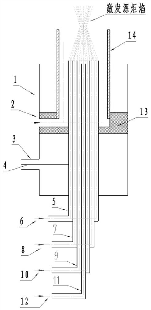
[0030] like figure 1 As shown in the figure, a microwave energy transmission part is an antenna-type microwave-coupled plasma and high-temperature flame fusion excitation source, including an outer conductor 1, a shielding gas inlet 2, a microwave input port 3, a microwave antenna 4, an inner conductor 5, an outer gas Inlet 6 , middle tube 7 , middle layer gas inlet 8 , inner tube 9 , inner layer gas inlet 10 , sample tube 11 , sample aerosol inlet 12 , guide ring 13 and guide tube 14 .

[0031] The microwave energy transmission part includes a microwave input port 3 and a microwave antenna 4 . Install L16-KF or L29-KF microwave connectors at microwave input port 3. One end of the microwave connector is connected to the microwave source, and the other end is connected to the microwave antenna 4 . The microwave antenna 4 is located at a distance λ / 4 from the bottom surface of the resonant cavity. An electrical connection is maintained between the microwave antenna 4 and the ...

Embodiment 2

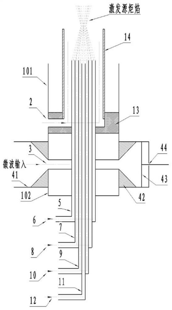
[0050] see figure 2 A microwave energy transmission part is a microwave coupling plasma and high temperature flame fusion excitation source in a waveguide mode, which is composed of a microwave energy transmission part and a microwave coaxial resonant cavity part.

[0051] The microwave energy transmission part includes a microwave input port 3 , a standard waveguide 41 , a waveguide-coaxial conversion cone 42 , a short-circuit piston 43 and an adjustment rod 44 . The microwave input port 3 is constituted by a gap formed between two waveguide-coaxial conversion cones 42 . The first port of the standard waveguide 41 is connected to the microwave generating system, the coaxial resonator outer conductor 1 is vertically installed on the upper outer wall in the length direction between the first port and the second port of the standard waveguide 41, and the lower inner wall in the length direction of the standard waveguide 41 is installed vertically. The waveguide-coaxial convers...


PUM

PropertyMeasurementUnit
impedanceaaaaaaaaaa

Abstract

The invention discloses a microwave coupling plasma and high-temperature flame fusion excitation source, and belongs to the technical field of analytical instruments. The device is composed of a microwave energy transmission part and a microwave coaxial resonant cavity part. The microwave coaxial resonant cavity part comprises an outer conductor (1), a shielding gas inlet (2), an inner conductor (5), an outer-layer gas inlet (6), a middle tube (7), a middle-layer gas inlet (8), an inner tube (9), an inner-layer gas inlet (10), a sample tube (11), a sample aerosol inlet (12), a flow guide ring (13) and a flow guide tube (14). Compared with the prior art, the excitation source disclosed by the invention has the advantages of fusion of plasma and high-temperature flame, high torch flame temperature, strong sample atomization capability and excitation capability and the like.

Description

technical field [0001] The invention belongs to the technical field of analytical instruments, in particular to a microwave-coupled plasma and high-temperature flame fusion excitation source that can be used in the fields of spectroscopy, mass spectrometry and chromatographic analysis. Background technique [0002] In the field of atomic spectroscopy, microwave discharge plasma as excitation source has the problems of low gas temperature and seriously insufficient atomization ability when measuring solution samples. In 1985, Jilin University created the Microwave Plasmas Torch (MPT) for the first time in the world. The resonator transforms the cylindrical solid electrode of the original resonator into a tubular electrode. The inner flow of the tubular electrode and the use of microwave electric field energy discharge to obtain the Ar-MPT excitation source is considered to be a "breakthrough progress" in microwave plasma research, which promotes the development of microwave p...

Claims


Application Information

Patent Timeline
Patent Type & Authority Applications(China)
IPC IPC(8): H05H1/46H05H1/26G01N21/31G01N21/64
CPCH05H1/461H05H1/26G01N21/3103G01N21/6402Y02E30/10
Inventor 高德江曹彦波费强宋大千
Owner JILIN UNIV
Why Eureka
Try Eureka