High-precision adjustable auxiliary machining equipment for neodymium-iron-boron magnet

An auxiliary processing, high-precision technology, applied in metal processing equipment, grinding/polishing equipment, manufacturing tools, etc. Location movement etc.

Active Publication Date: 2022-03-22
深圳市东方熊磁电制品有限公司
View PDF13 Cites 1 Cited by
  • Summary
  • Abstract
  • Description
  • Claims
  • Application Information

AI Technical Summary

Problems solved by technology

[0003] At present, when chamfering the inner or outer corners of the ring-shaped NdFeB magnets, it is often necessary for the operator to manually exchange the two ends of the ring NdFeB magnets for grinding, and after changing the positions of the two ends of the ring NdFeB magnets, the device is still only It can chamfer a group of circular NdFeB magnets, but cannot chamfer two sets of circular NdFeB magnets at the same time; and the current auxiliary processing equipment for circular NdFeB magnets still requires operators to manually process Remove the good ring NdFeB magnets and replace them with a new set of ring NdFeB magnets. During the process of replacing the ring NdFeB magnets, the operator's hands are relatively close to the chamfering and grinding structure of the device. , it is easy to cause accidental damage, and it is impossible to automatically replenish the non-chamfered circular NdFeB magnets into the processing equipment; at the same time, the current auxiliary processing equipment of the circular NdFeB magnets is grinding the circular NdFeB magnets of different calibers. When the magnet is used, it is necessary to replace the corresponding fixed structure, which is very inconvenient. It is impossible to make the auxiliary processing equipment suitable for more caliber ring NdFeB magnets, and it is also impossible to automatically move the position of the ring NdFeB magnet to the chamfer The corresponding chamfer of the device

Method used


Image

  • High-precision adjustable auxiliary machining equipment for neodymium-iron-boron magnet
  • High-precision adjustable auxiliary machining equipment for neodymium-iron-boron magnet
  • High-precision adjustable auxiliary machining equipment for neodymium-iron-boron magnet

Examples


Embodiment 1

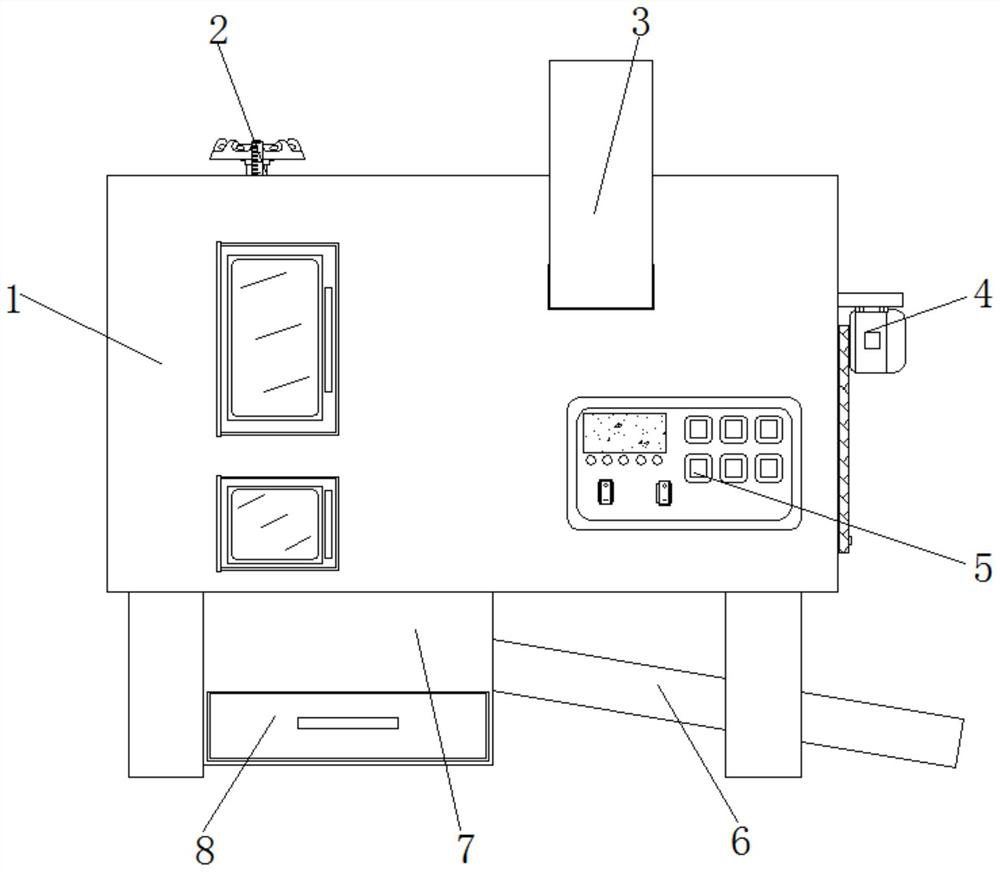
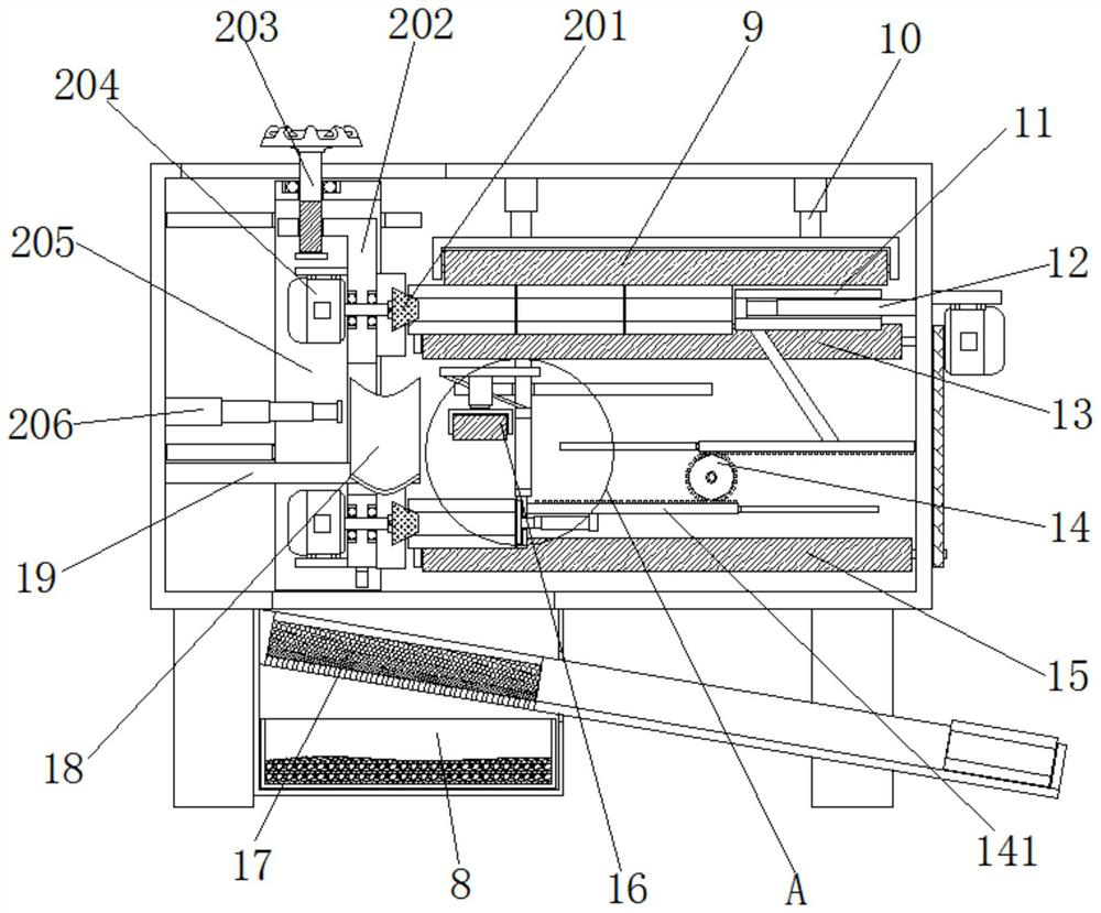
[0041] Example 1, such as figure 1 , 2 , 3, 4, 5, 8 and 10, when starting to chamfer the ring NdFeB magnet, first according to the actual diameter of the ring NdFeB magnet, compare the scale on the height scale plate 207 manually Rotate threaded rod 203, because of the effect of screw thread, force L-shaped plate 202 to rise or fall in the inside of U-shaped movable chamber 205, thereby precisely adjust the center of grinding head 201, make it and two groups of first lower installation rollers 13 circles The center of the ring NdFeB magnet is aligned, and then the operator only needs to manually place the ring NdFeB magnet horizontally into the interior of the feeding guide bin 3, and the processed ring NdFeB magnet is moved to the row The inside of the chute 6 is far away from the end of the fixed plate 19. During the whole process, the operation can easily supplement the processing raw materials to the inside of the feeding guide bin 3, and can also easily remove the proces...

Embodiment 2

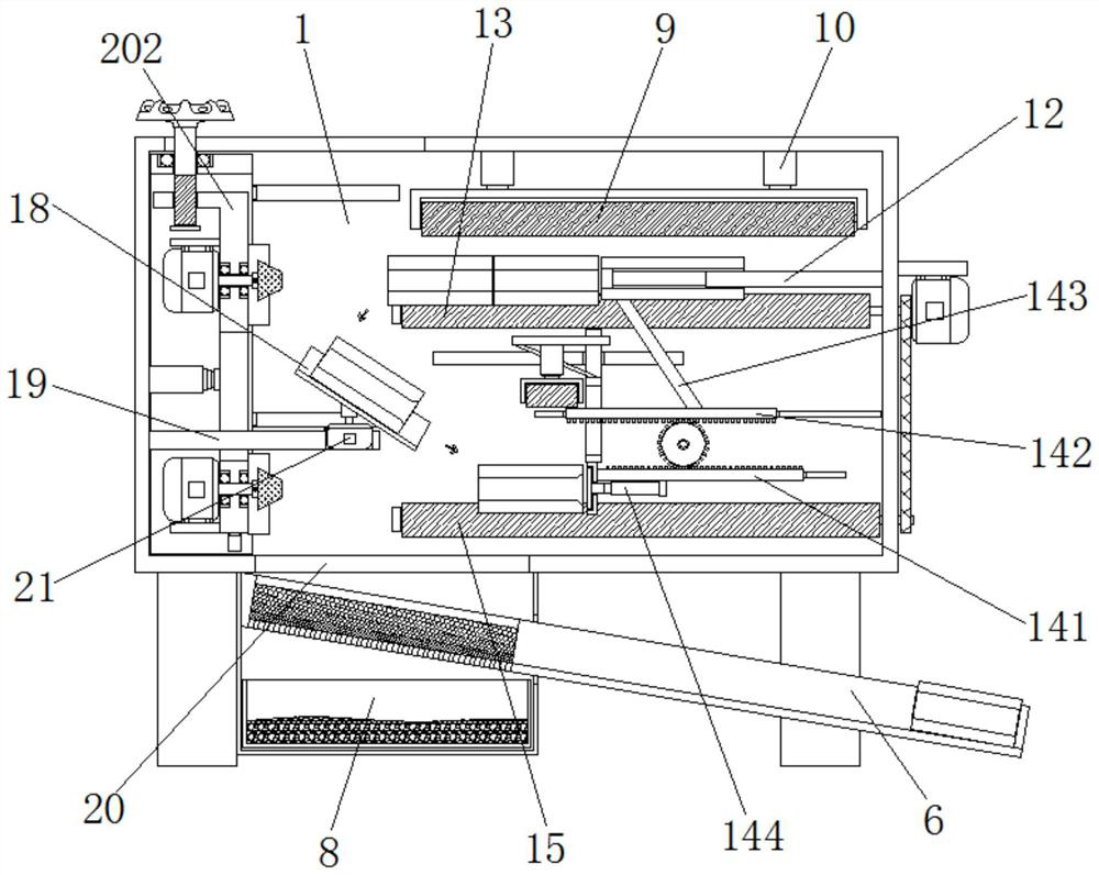
[0042] Example 2, such as Figure 2-4 As shown, control the first electric lifting rod 206 to shorten, control the first electric push rod 12 to extend, and control the servo motor 21 to drive the arc-shaped material guide plate 18 to rotate counterclockwise 90°, and then the first electric push rod 12 can be controlled Elongate, use the push tube 11 to push the ring NdFeB magnets between the first two sets of lower installation rollers 13 to move to the end close to the fixed plate 19, until the first set of ring NdFeB magnets flip and fall to the arc Shaped material guide plate 18, along the guide of arc-shaped material guide plate 18, falls between two groups of second lower mounting rollers 15, and at this moment, the end of the first group of ring NdFeB magnets that is not chamfered Already facing the second group of grinding heads 201, the automatic direction adjustment of the equipment to the ring NdFeB magnets has been realized, and the ring NdFeB magnets between the t...

Embodiment 3

[0043] Example 3, such as Figure 2-5As shown, after the equipment automatically adjusts the direction of the ring NdFeB magnets, it controls the first electric push rod 12 to shorten back to the original length. At this time, the gap between the third group of ring NdFeB magnets and the push tube 11 There is a vacancy for a ring NdFeB magnet. After the inner ring NdFeB magnet of the feed guide bin 3 loses its limit by the push tube 11, a group of ring NdFeB magnets at the bottom of the feed guide bin 3 The boron magnet automatically falls into the space under the influence of gravity to realize the automatic feeding function of the equipment. When the first electric push rod 12 is extended, the first group of circular NdFeB rings between the two sets of first lower installation rollers 13 are extended. When the magnet is pushed down, due to the transmission of the lower rack plate 141, the upper rack plate 142 and the transmission gear 145, the outer pusher plate 146 and the ...


PUM


Abstract

The high-precision adjustable auxiliary machining equipment comprises a main body bin, first lower mounting rollers are symmetrically arranged in the middle positions of the two sides in the main body bin, and second lower mounting rollers are symmetrically arranged at the bottoms of the ends, close to the first lower mounting rollers, of the two sides in the main body bin; and two groups of second electric lifting rods are mounted at one end, close to the first lower mounting roller, of the top in the main body bin. A servo motor is controlled to drive an arc-shaped material guide plate to rotate by 90 degrees anticlockwise, then a first electric push rod can be controlled to extend, and a material pushing pipe is used for pushing a circular ring neodymium-iron-boron magnet between two groups of first lower mounting rollers to move towards one end close to a fixed plate until the first group of circular ring neodymium-iron-boron magnets are overturned and fall into the arc-shaped material guide plate; and at the moment, the unchamfered ends of the first group of circular neodymium-iron-boron magnets face the second group of polishing heads, so that the automatic direction adjustment of the circular neodymium-iron-boron magnets by the equipment is realized.

Description

technical field [0001] The invention relates to the technical field of auxiliary processing equipment for NdFeB magnets, in particular to a high-precision adjustable auxiliary processing equipment for NdFeB magnets. Background technique [0002] NdFeB magnets are tetragonal crystals formed of neodymium, iron, and boron. In 1982, Masato Sagawa discovered neodymium magnets. The magnetic energy product of this magnet was greater than that of samarium cobalt magnets, and it was the material with the largest magnetic energy product in the world at that time. , and successfully developed the powder metallurgy method. General Motors successfully developed the spin-spray smelting method, which can produce NdFeB magnets. This kind of magnet is the permanent magnet that is second only to the absolute zero holmium magnet, and it is also the most commonly used rare earth magnet. NdFeB magnets are widely used in electronic products, and circular NdFeB magnets are one of the commonly used...

Claims


Application Information

Patent Timeline
Patent Type & Authority Applications(China)
IPC IPC(8): B24B9/04B24B27/00B24B41/06B24B41/00
CPCB24B9/04B24B27/0076B24B27/0092B24B41/06B24B41/00
Inventor 熊迎松李艮秀
Owner 深圳市东方熊磁电制品有限公司
Why Eureka
Try Eureka