Optical fiber drawing furnace

A technology for optical fibers and wire drawing furnaces, applied in glass manufacturing equipment, manufacturing tools, etc., can solve problems such as many surface defects of optical fiber wires, stacking of furnace wires, and large temperature fluctuations, so as to improve production efficiency and operation safety. The effect of stable diameter and ovality and high precision of wire diameter

Active Publication Date: 2022-03-22
CHINA BUILDING MATERIALS ACAD
View PDF8 Cites 0 Cited by
  • Summary
  • Abstract
  • Description
  • Claims
  • Application Information

AI Technical Summary

Problems solved by technology

The existing drawing furnaces for preparing optical fibers for optical fiber image transmission components mainly have three disadvantages: one is the use and operation of special requirements such as atmosphere furnaces, vacuum furnaces, etc. These drawing furnaces have complex structures, high manufacturing and maintenance costs, and difficult to operate. Complex, for the preparation of optical fiber image transmission components, this special structure of the drawing furnace can not meet the production needs of frequent heating and cooling operations; the second is the ordinary electric furnace wire heating furnace, this kind of wire drawing furnace is threaded or wound by the furnace wire. Realize heating, the structure is simple, but in order to achieve the temperature required for wire drawing, the temperature zone of the furnace is often wide, the heat preservation is poor, the heat dissipation is serious, and the safety is poor. Moreover, due to frequent heating and cooling and long-term heating, the furnace wires are easy to stack or collapse. This leads to short service life and frequent replacement, resulting in poor process stability, uneven furnace temperature, and poor temperature stability, which eventually lead to crystallization or bursting of the drawn preform, resulting in many surface defects of the optical fiber filaments, tiny cracks, internal The structure is not tight, the stability of the wire diameter is poor, etc.; the third is that the sealing between the insulation material and the furnace body is not good, which leads to dust pollution in the drawing furnace, which cannot meet the requirements for drawing optical fiber filaments in a clean environment above 10,000 of
If the heat generation of the heating element of the drawing furnace is not uniform along the circumferential direction, the optical fiber may have a non-uniform cross-section, and when the optical fiber has a large ellipticity, it will cause shear distortion or Internal defects such as spots, grids, chicken wire, etc.
[0007] The various wire drawing furnaces currently used cause many defects or tiny cracks on the surface of the drawn optical fiber, the internal structure is poor and not compact, and the wire diameter stability of the drawn optical fiber is poor, and the temperature uniformity of the drawing furnace is not good. Well, the temperature fluctuates greatly, the service life is short, and the replacement is frequent, which affects the production stability of the optical fiber image transmission components

Method used


Image

  • Optical fiber drawing furnace
  • Optical fiber drawing furnace
  • Optical fiber drawing furnace

Examples


Embodiment Construction

[0041] In order to make the purpose, technical solutions and advantages of the embodiments of the present invention clearer, the technical solutions in the embodiments of the present invention will be clearly and completely described below in conjunction with the drawings in the embodiments of the present invention. Obviously, the described embodiments It is a part of embodiments of the present invention, but not all embodiments. Based on the embodiments of the present invention, all other embodiments obtained by persons of ordinary skill in the art without making creative efforts belong to the protection scope of the present invention.

[0042] The method for drawing optical fiber using the optical fiber drawing furnace of the present invention will be described below through specific embodiments.

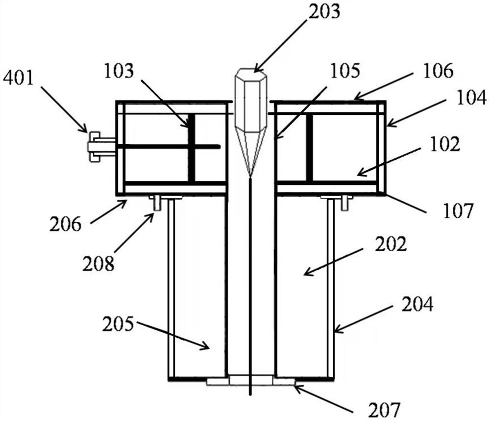
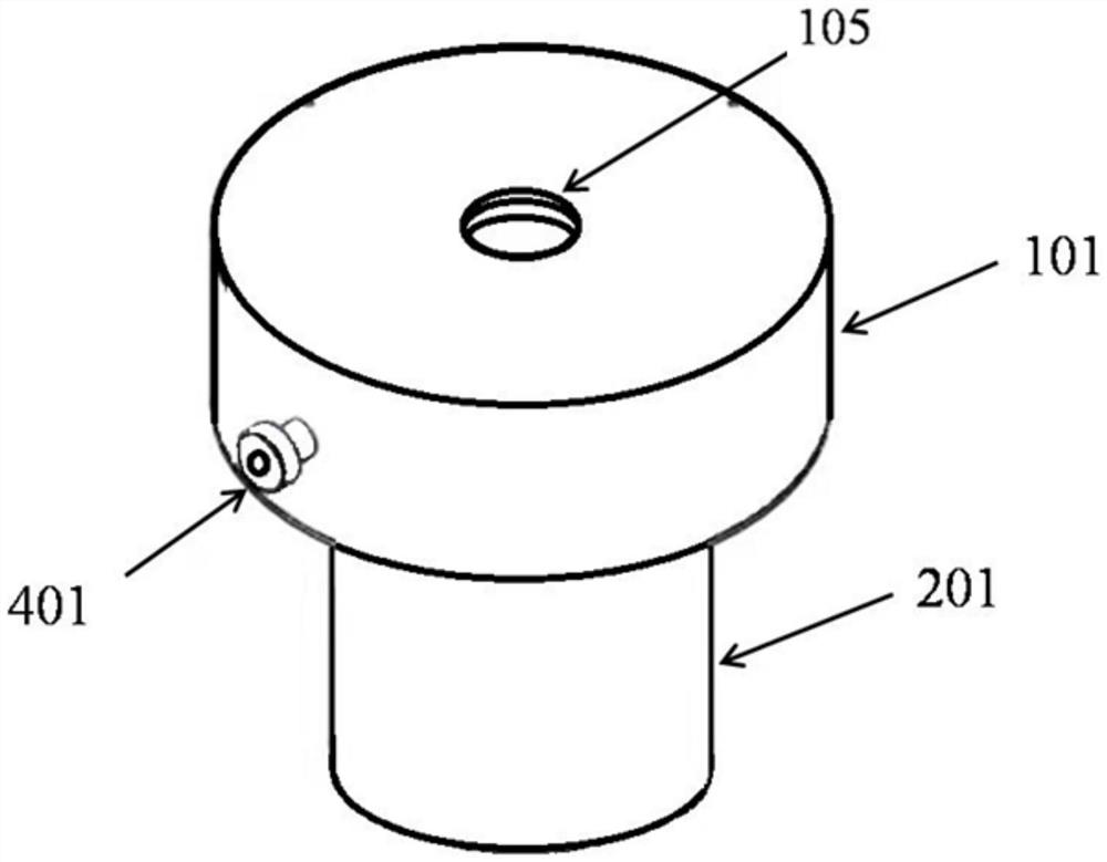
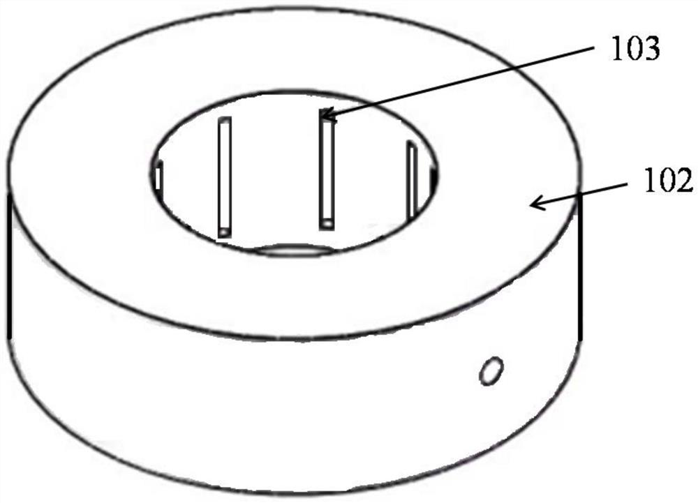
[0043] see figure 1 , figure 2 and image 3 , an optical fiber drawing furnace, comprising a heating furnace body 101 and a support body 201 arranged below the heating furnace...


PUM

PropertyMeasurementUnit
diameteraaaaaaaaaa
heightaaaaaaaaaa
thicknessaaaaaaaaaa

Abstract

The invention discloses an optical fiber drawing furnace which comprises a heating furnace body and a supporting body arranged below the heating furnace body. The heating furnace body comprises a hollow hearth and a bottom plate, heating furnace wires are evenly arranged on the inner walls of the periphery of the hearth, the bottom plate is located at the bottom of the hearth, a hollow temperature equalizing body is arranged on the bottom plate and located in the hearth, and the center of a cavity of the temperature equalizing body coincides with the center of a cavity of the hearth. The supporting body comprises a wire drawing channel located in the middle, the wire drawing channel is communicated with the cavity of the temperature equalizing body, and the center of the cavity of the temperature equalizing body coincides with the center of the wire drawing channel. By designing the hearth with the narrow high-temperature area, the utilization rate of raw materials for wire drawing is increased, the structure is simple, disassembly and replacement are easy, the temperature field in the wire drawing hearth is stable and uniform, the heat preservation effect is good, energy is saved, environment friendliness is achieved, and drawn optical fibers are stable in fiber diameter and ovality, excellent in surface quality and few in surface defect.

Description

technical field [0001] The invention relates to the technical field of optical fiber manufacturing and processing, in particular to an optical fiber drawing furnace. Background technique [0002] Optical fiber imaging components, including optical fiber panels, optical fiber inverters, optical fiber cones, optical fiber imaging bundles, and microchannel plates, are photoelectric imaging components with excellent performance, with simple structure, small size, and light weight. , high resolution, large numerical aperture, small inter-stage coupling loss, clear and true image transmission, high light transmission efficiency, optical zero thickness in image transmission, and improved edge image quality. Optical fiber image transmission components are widely used in various cathode ray tubes, camera tubes, charge-coupled device (CCD, Charge-coupled Device) couplings, medical device display screens and high-speed High-definition television imaging and other instruments and equip...

Claims


Application Information

Patent Timeline
Patent Type & Authority Applications(China)
IPC IPC(8): C03B37/029
CPCC03B37/029Y02P40/57
Inventor 张磊樊志恒张敬许慧超于浩洋贾金升张弦汤晓峰赵越
Owner CHINA BUILDING MATERIALS ACAD
Why Eureka
Try Eureka