
Hydrogen compression material as well as preparation method and application thereof

A technology of hydrogen compressor and inert gas, which is applied in the field of hydrogen compression materials and its preparation, can solve the problems of waste in storage and transportation, and achieve the effects of reducing overall cost, stability, platform slope and hysteresis

Active Publication Date: 2022-03-22
SOUTH CHINA UNIV OF TECH
View PDF6 Cites 1 Cited by
  • Summary
  • Abstract
  • Description
  • Claims
  • Application Information

AI Technical Summary

Problems solved by technology

However, limited by the compression ratio, the mechanical hydrogen compressor can only pressurize the hydrogen above 6MPa at the minimum, so the gas below 6MPa in the long tube trailer can only be transported back, which will cause huge waste in the storage and transportation link

Method used


Image

  • Hydrogen compression material as well as preparation method and application thereof
  • Hydrogen compression material as well as preparation method and application thereof
  • Hydrogen compression material as well as preparation method and application thereof

Examples


Embodiment 1

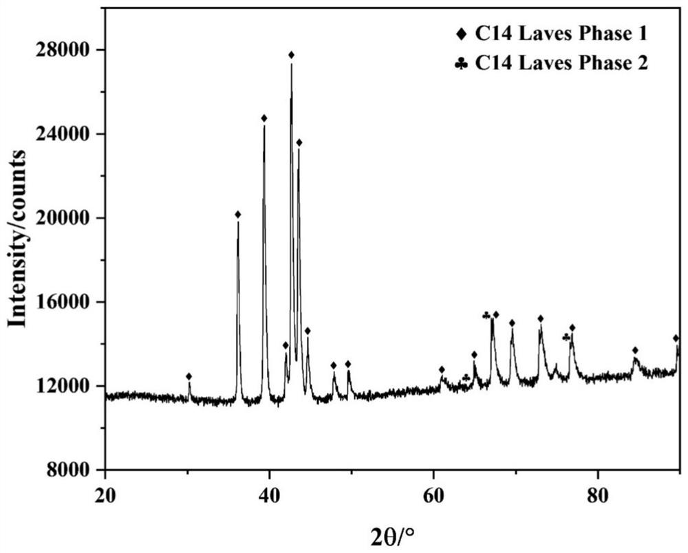
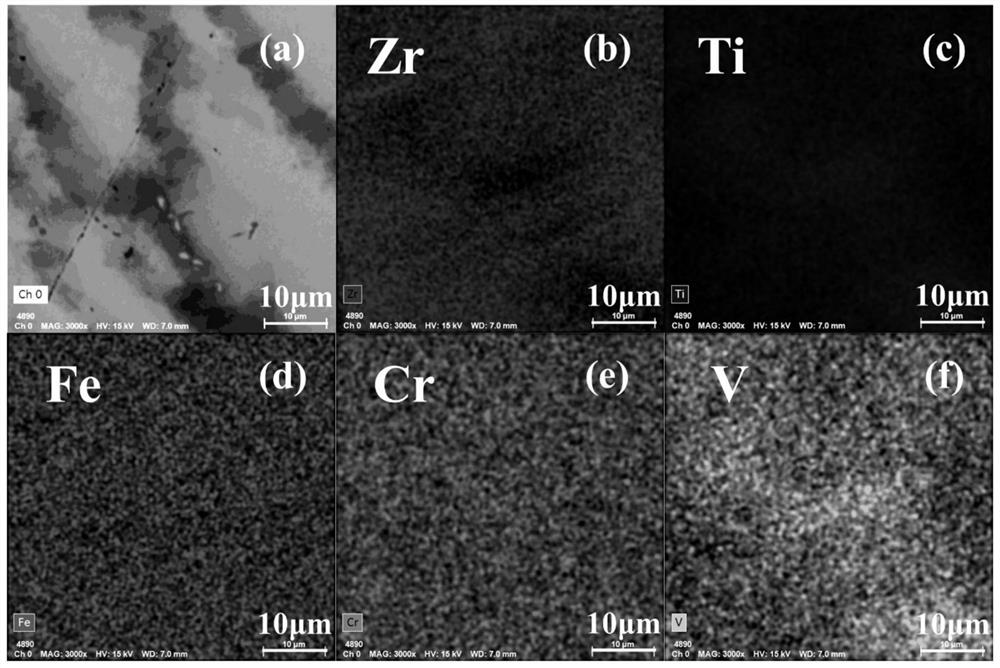
[0041] (1) Put 3.3865gZr, 0.7681gTi, 0.5538g Cr, 5.0342g Fe and 0.2714g V with a purity of more than 99.9% into the crucible of the electric arc melting furnace, cover the furnace cover, and vacuum the furnace chamber until the vacuum degree is 3×10 -3 Pa, filled with argon to a pressure of 0.06MPa, and melted in an arc higher than 1600°C. After that, the residual oxygen in the furnace chamber is absorbed by melting the pre-placed pure zirconium blocks in the furnace chamber by electric arc. In order to improve the uniformity, each sample was turned over and remelted 5 times, each melting time was about 30s, and 9.9950g ingot was obtained after cooling by a water-cooled copper mold for 15min. The theoretical composition of the alloy ingot is Zr 0.7 Ti 0.3 Fe 1.7 Cr 0.2 V 0.1 .

[0042] (2) Grinding the alloy ingot in step (1) with a grinder to remove surface scale. The alloy was then crushed into a powder state in a glove box, and screened with a 100-mesh sieve to obtai...

Embodiment 2~5

[0049] The alloy compositions and hydrogen storage thermodynamic properties of Examples 2-5 are shown in Table 1, and the preparation process is the same as that of Example 1.

[0050] Zr in table 1 embodiment 2-5 1-x Ti x Fe 1.7 Cr 0.2 V 0.1 Hydrogen Storage Thermodynamic Properties of (x=0,0.1,0.2,0.4) Alloys

[0051]

[0052]

[0053] *The plateau pressure values ​​of the alloys at 298K and 333K are extrapolated from the van't Hoff equation.

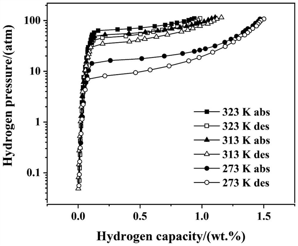
[0054] Figure 6(a), Figure 6(b), Figure 6(c), Figure 6(d) are Zr 1-x Ti x Fe 1.7 Cr 0.2 V 0.1 (x=0,0.1,0.2,0.4) alloy PCI curve, it can be observed that with the increase of Ti to Zr substitution, the hydrogen desorption plateau pressure of the alloy at the same temperature (273K) is significantly increased, and the hydrogen storage capacity is significantly reduced . In addition, the proportion of the α hydrogen solid solution region in the PCI curve decreases, and the proportion of the β hydride phase region increas...


PUM


Abstract

The invention discloses a hydrogen compression material, the structural general formula of which is Zr < 1-x > Ti < x > Fe < 1.7 > Cr < 0.2 > V < 0.1 >, and x is equal to 0.1-0.4. The invention also discloses a preparation method of the hydrogen compression material, which comprises the following steps: weighing the metal zirconium, titanium, iron, chromium and vanadium according to the structural general formula, mixing, placing in a crucible, cleaning with inert gas, vacuumizing, filling the inert gas, and smelting under an electric arc condition to obtain the hydrogen compression material. The invention also discloses application of the hydrogen compression material as a self-pressurization hydrogen storage material of a mechanical hydrogen compressor of a hydrogen refueling station. The hydrogen compression material absorbs 4-6 MPa hydrogen at room temperature by using waste heat generated by a mechanical hydrogen compressor, and discharges hydrogen at a pressure of 6 MPa or more at 60 DEG C. The hydrogen compression material has the advantages that the platform width is large, and the effective hydrogen compression amount in the working temperature range is large.

Description

technical field [0001] The invention relates to a hydrogen storage material, in particular to a hydrogen compression material and its preparation method and application. Background technique [0002] Metal hydride hydrogen compressors use hydrogen storage alloys (hydrogen compression materials) to boost pressure at different temperatures. The alloy absorbs low-pressure hydrogen at low temperature and releases high-pressure hydrogen at high temperature. The whole process follows the Van’t Hoff equation In addition, the temperature rise in the pressurization process of the system can be provided by the heat generated by the friction drive of the mechanical hydrogen compressor, which can effectively utilize waste heat and achieve the purpose of energy saving and environmental protection. [0003] ZrFe 2 It is one of the common high-pressure hydrogen storage alloys. It has a Laves phase structure, a dehydrogenation pressure of up to 33MPa at room temperature, and a small α-hy...

Claims


Application Information

Patent Timeline
Patent Type & Authority Applications(China)
IPC IPC(8): C22C38/14C22C38/18C22C38/12C22C30/00C22C33/04C01B3/00
CPCC22C38/14C22C38/18C22C38/12C22C30/00C22C33/04C01B3/0031Y02E60/32Y02P20/129
Inventor 欧阳柳章彭琢雅王辉曾美琴朱敏
Owner SOUTH CHINA UNIV OF TECH
Learn More