Full-automatic high-flux homogenizer

A homogenizer, high-throughput technology, applied in chemical instruments and methods, dry solid materials, preparation of samples for testing, etc., can solve the problems of installation, disassembly, difficulty in replacement, slow replacement, etc. clean effect

Pending Publication Date: 2022-03-25
上海奥然科贸有限公司
View PDF0 Cites 0 Cited by
  • Summary
  • Abstract
  • Description
  • Claims
  • Application Information

AI Technical Summary

Problems solved by technology

[0003] The purpose of the present invention is to provide a fully automatic high-throughput homogenizer, which solves the problem that the cutter head of the fully automatic high-throughput cutter head homogenizer is mostly replaced by twisting threads, and there are difficulties in installation, disassembly and replacement, and slow replacement speed

Method used


Image

  • Full-automatic high-flux homogenizer
  • Full-automatic high-flux homogenizer
  • Full-automatic high-flux homogenizer

Examples


Embodiment 1

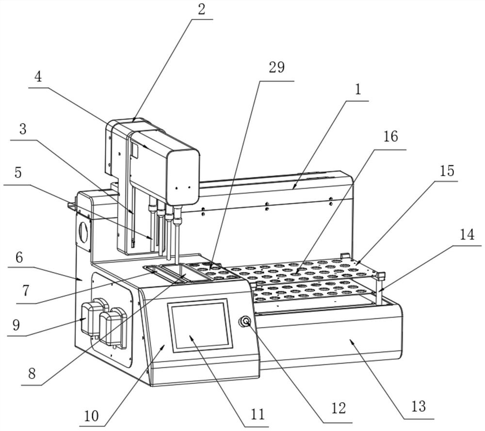
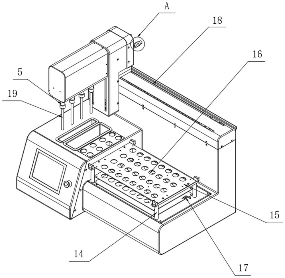
[0021] see Figure 1-4 , the present invention provides a technical solution: a fully automatic high-throughput homogenizer, including a homogenizer sliding table 1, a sliding connecting rod 2 is detachably installed on the top of one side of the homogenizing device sliding table 1, and the sliding connecting rod The top of one side of 2 is provided with a Z-axis screw slide rail 3, the top of one side of the sliding connecting rod 2 is detachably installed with a homogenizer controller 4, and the bottom end of the homogenizer controller 4 is detachably installed with a homogenizer head 5 A control base 6 is fixedly installed on one side of the homogenizer slide table 1, and a flow washing pool 7 is provided inside the control base 6, and an ultrasonic cleaning pool 8 is provided on one side of the flow washing pool 7, and an ultrasonic cleaning pool 8 is provided on one side of the ultrasonic cleaning pool 8. A custom cleaning pipe rack 29 is fixedly installed, a peristaltic ...

Embodiment 2

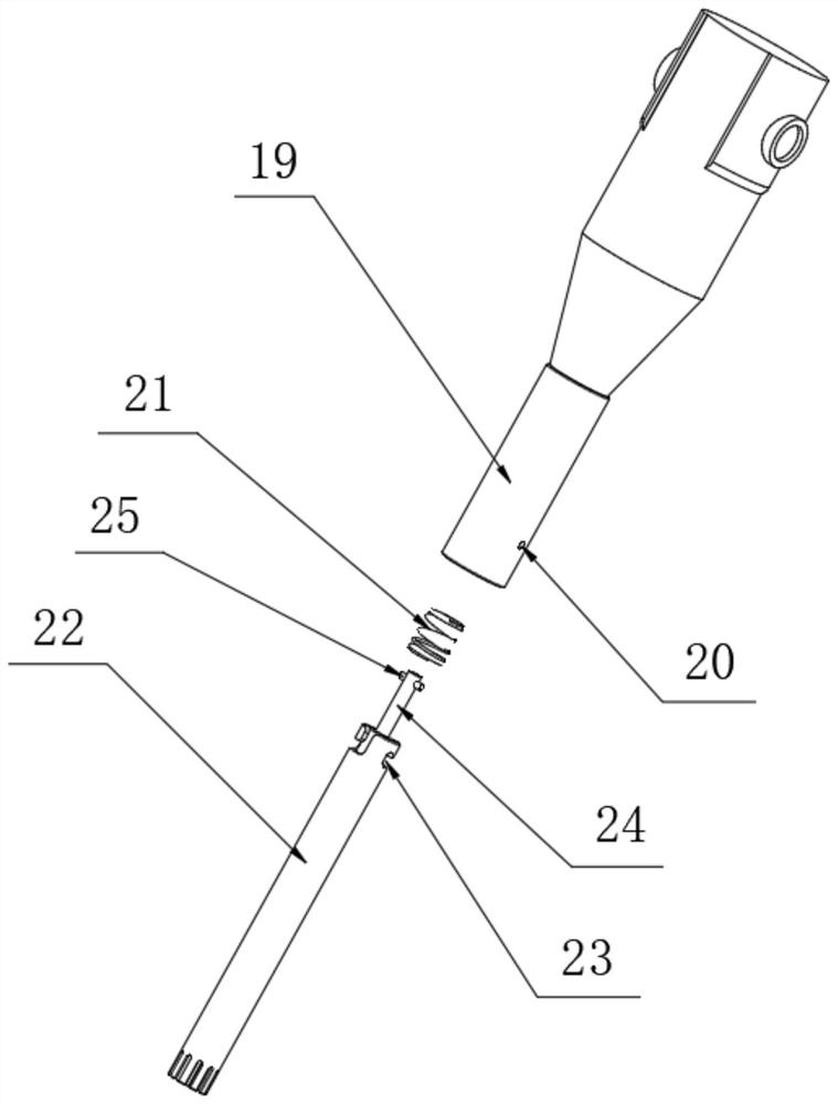
[0024] see Figure 1-4 As shown, on the basis of Embodiment 1, the present invention provides a technical solution: the surface of the quick-connect sleeve 19 is provided with a positioning pin 20, and the inside of the positioning pin 20 is detachably installed with a spring 21, and the quick-connect sleeve 19 One side is detachably equipped with homogenizing rod 22, and the top of one side of homogenizing rod 22 is provided with homogenizing cutter head introduction groove 23, and the inside of homogenizing cutter head introducing groove 23 is detachably installed with sleeve rod 24, sleeve rod The top on one side of 24 is fixedly equipped with a buckle rod 25, and the connection relationship between the homogenizing cutter head introduction groove 23 and the positioning pin 20 is movable clamping connection, and the back side of the sliding connecting rod 2 is detachably equipped with a circuit box 26, and the circuit box 26- A circuit connector 27 is detachably installed o...


PUM


Abstract

The invention discloses a full-automatic high-flux homogenizer and relates to the technical field of homogenizers, the homogenizer comprises a homogenizer sliding table, a sliding connecting rod is detachably mounted at the top end of one side of the homogenizer sliding table, and a Z-axis lead screw sliding rail is arranged at the top end of one side of the sliding connecting rod; a homogenate controller is detachably mounted at the top end of one side of the sliding connecting rod. When the homogenate tool bit processes samples in a certain column of sample tubes and stops rotating, the homogenate tool bit is lifted to leave the homogenate, the tail end of the homogenate tool bit is located below a sample tube opening and above the liquid level, at the moment, a program issues an instruction of short-time operation of the homogenate controller, the homogenate controller operates to drive the homogenate tool bit to idle at a high speed for a short time, and the homogenate tool bit stops rotating. When the homogenizer is used, residual homogenate at the tail end of the homogenate cutter head is thrown into the sample tube, so that cross contamination caused by the fact that the residual homogenate drips to other sample tubes when the homogenate cutter head moves above the sample tube is avoided, and then the equipment enters an automatic cleaning procedure.

Description

technical field [0001] The invention relates to the technical field of homogenizers, in particular to a fully automatic high-throughput homogenizer. Background technique [0002] It involves experiments and inspection fields such as biological sciences, environmental sciences, food sciences, pharmaceuticals, and cosmetics. The fields of experiments and inspections such as biological sciences, environmental sciences, food sciences, pharmaceuticals, and cosmetics require the use of fully automatic high-throughput homogenizers. The cutter heads of the fully automatic high-throughput cutter head homogenizers used in experiments or production fields such as science, environmental science, food science, medicine, and cosmetics are mostly replaced by twisting threads, which are difficult to install, disassemble, and replace, and the replacement speed is slow. problem; and when the cutter head moves above the sample tube, there is a drop of homogenate residue, and the cleaning is no...

Claims


Application Information

Patent Timeline
IPC IPC(8): G01N1/38B08B3/04B08B3/08B08B3/12B08B7/00B08B7/04F26B5/08
CPCG01N1/38B08B7/00B08B7/04B08B3/041F26B5/08B08B3/123B08B3/08
Inventor 侯磊
Owner 上海奥然科贸有限公司
Why Eureka
Try Eureka