Radar calibration method, radar, upper computer, calibration system and storage medium
A radar calibration and radar technology, applied in the calibration system and storage media, host computer, radar calibration method, radar field, can solve the problems of detection result error, reflection time error, etc., and achieve the effect of improving detection accuracy
- Summary
- Abstract
- Description
- Claims
- Application Information
AI Technical Summary
Problems solved by technology
Method used
Image

Examples
Embodiment 1
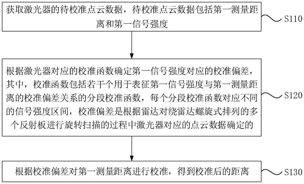
[0036] In the embodiment of the present invention, figure 1 It is a flowchart of a radar calibration method provided by Embodiment 1 of the present invention, and this embodiment of the present invention is applicable to radar calibration. Embodiments of the present invention may be implemented by lidar. Such as figure 1 As shown, the embodiment of the present invention includes the following steps:
[0037] S110. Acquire point cloud data of the laser to be calibrated, where the point cloud data to be calibrated includes a first measurement distance and a first signal strength.
[0038] It should be noted that the radar can include one or more lasers, and the laser can be used to emit laser light, which is reflected back when encountering a target object, and the point cloud data to be calibrated can be obtained according to the speed of light and propagation time, wherein the point cloud data to be calibrated can include A first measured distance and a first signal strengt...
Embodiment 2
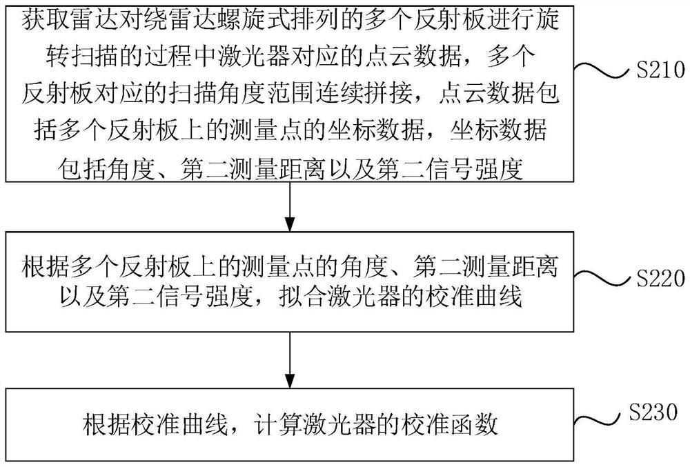
[0050] figure 2 It is a flow chart of another radar calibration method provided by the second embodiment of the present invention. The embodiment of the present invention can be executed by the host computer, see figure 2 , the method provided in the embodiment of the present invention specifically includes the following steps:
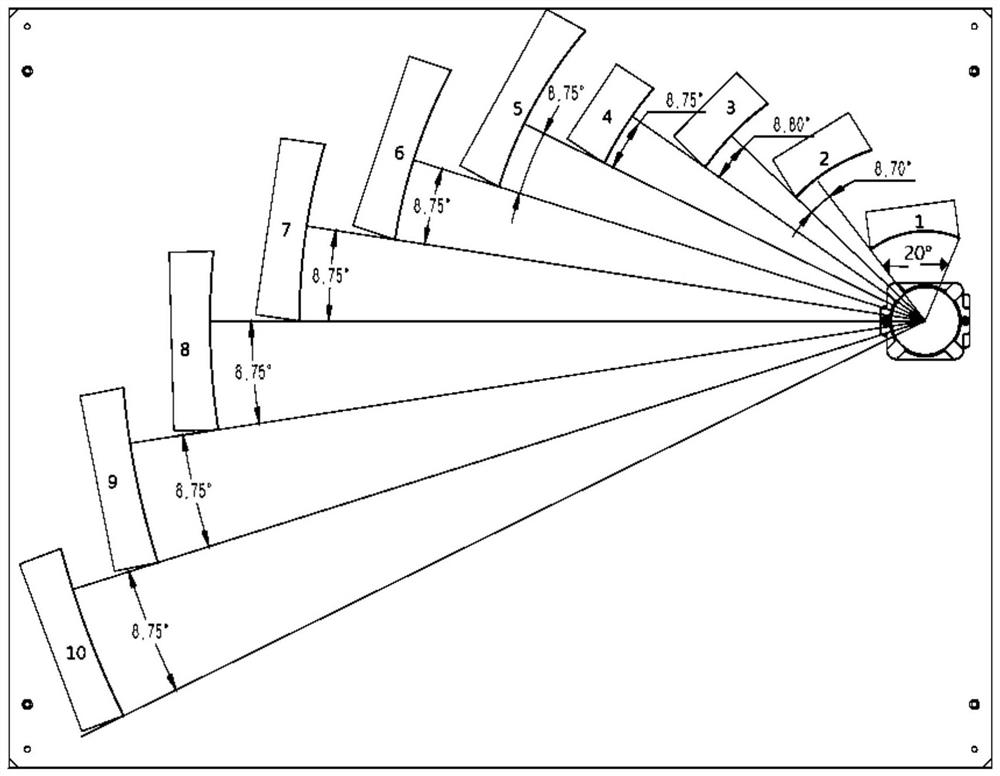
[0051] S210. Obtain the point cloud data corresponding to the laser during the process of the radar rotating and scanning the multiple reflectors arranged in a spiral around the radar. The scanning angle ranges corresponding to the multiple reflectors are continuously spliced, and the point cloud data includes the points on the multiple reflectors. Coordinate data of the measurement point, where the coordinate data includes an angle, a second measurement distance, and a second signal strength.
[0052] It should be noted that the radar may include one or more lasers, and point cloud data may be obtained using the lasers. The point cloud data can b...
Embodiment 3
[0086] Figure 5 It is a schematic structural diagram of a radar provided in Embodiment 3 of the present invention. Figure 5 A block diagram of a radar 312 suitable for use in implementing embodiments of the invention is shown. Figure 5 The displayed radar 312 is only an example, and should not impose any limitation on the functions and scope of use of the embodiments of the present invention.
[0087] Such as Figure 5 As shown, the components of the radar 312 may include, but are not limited to: at least one laser 341; one or more processors 316 electrically connected to the laser 341; a storage device 328 connected to different system components (including the storage device 328 and the processor 316) bus 318 .
[0088] Bus 318 represents one or more of several types of bus structures, including a memory bus or memory controller, a peripheral bus, an accelerated graphics port, a processor, or a local bus using any of a variety of bus structures. For example, these arc...
PUM
 Abstract
Description
Claims
Application Information
 - R&D Engineer
- R&D Manager
- IP Professional
- Industry Leading Data Capabilities
- Powerful AI technology
- Patent DNA Extraction
Browse by: Latest US Patents, China's latest patents, Technical Efficacy Thesaurus, Application Domain, Technology Topic.
© 2024 PatSnap. All rights reserved.Legal|Privacy policy|Modern Slavery Act Transparency Statement|Sitemap