Millimeter wave phased-array antenna array integration adapter

A technology of phased array antennas and conversion joints, which is applied in the directions of antenna arrays, antenna arrays that are energized separately, and antenna grounding devices. The effect of small weight and volume

Pending Publication Date: 2022-03-25
上海微波技术研究所(中国电子科技集团公司第五十研究所)
View PDF1 Cites 0 Cited by
  • Summary
  • Abstract
  • Description
  • Claims
  • Application Information

AI Technical Summary

Problems solved by technology

[0005] Patent document CN206516752U discloses a tile-type phased array antenna based on a tile structure, a millimeter-wave 64-element tile-type phased array antenna, including a 2*2 TR component array, and the number of sub-array channels of each TR component is 4*4, a total of 64 Sub-array channel; each TR component includes a transceiver channel module, a power module, a control module and a structural cavity, the power module is connected to the external interface, the power module and the control module are vertically interconnected through pins, and the control module and the transceiver channel module are connected through gold wires The three modules are placed in parallel in turn, but this design still cannot solve the problem of compact structure and good consistency of RF interconnection

Method used


Image

  • Millimeter wave phased-array antenna array integration adapter
  • Millimeter wave phased-array antenna array integration adapter
  • Millimeter wave phased-array antenna array integration adapter

Examples


Embodiment 1

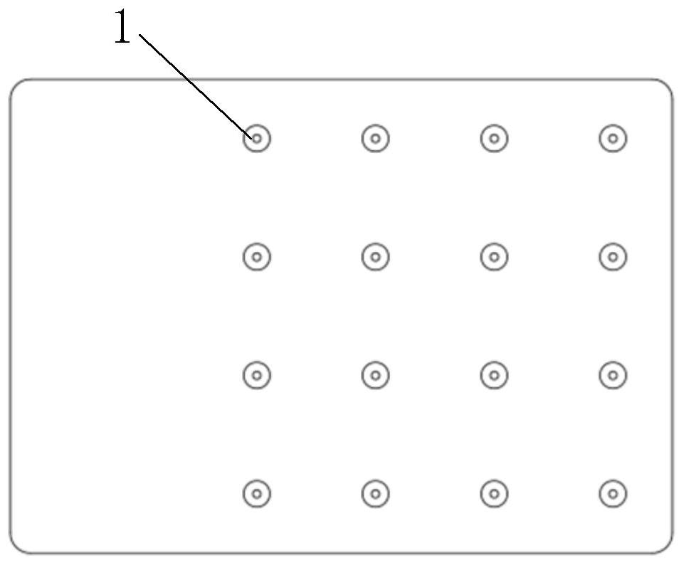
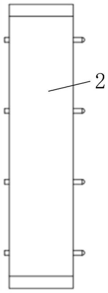
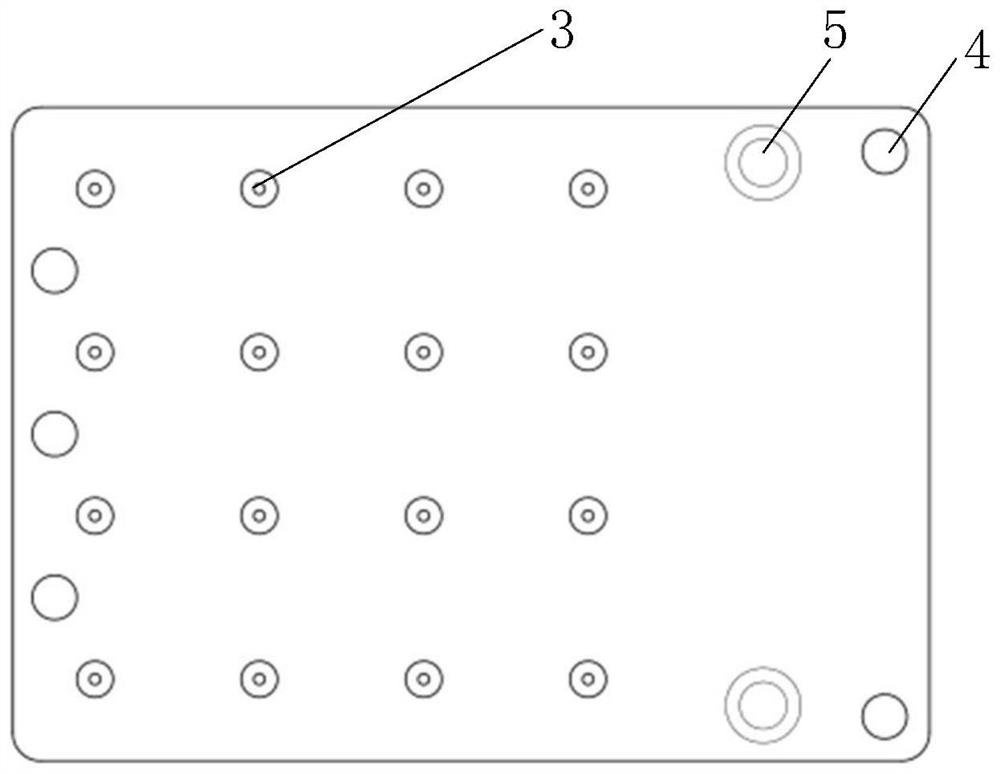
[0040] The present invention provides a millimeter-wave phased array antenna array integrated conversion connector, including a metal ground 2, a terminal 1 arranged on the front of the metal ground 2, and a metal pin 3 arranged on the back of the metal ground 2, and the terminal 1 and the metal pin 3 are one A corresponding connection forms an inner conductor, and the terminal 1 adopts an elastic structure, such as an elastic stretchable fur button. The metal ground 2 is an outer conductor and the terminals 1 on the front of the metal ground 2 or the metal pins 3 on the back are arranged in an array, and the terminals 1 on the front of the metal ground 2 or the metal pins 3 on the back are preferably arranged in a 4*4 array. An impedance medium is filled between the inner conductor and the outer conductor and matched to 50 ohms. The impedance medium is preferably made of Teflon.

[0041] The distance between two adjacent terminals 1 or two adjacent metal needles 3 is half the...

Embodiment 2

[0045] This embodiment is a preferred example of Embodiment 1.

[0046] In this example, if figure 1 , figure 2 , image 3 As shown, the integrated conversion joint 7 includes 16 positive elastic terminals 1, metal ground 2, and 16 reverse metal pins 3, wherein the front terminal 1 and the reverse metal pin 3 are interconnected, and the millimeter wave signal is connected between the terminal 1 and the metal pin 3 transfer between.

[0047] The terminals 1 and the metal pins 3 are arranged in a 4*4 array, and the arrangement spacing is 1 / 2 of the working wavelength, and the specific size is determined by the working center frequency. The diameter of the terminal 1 is 0.4mm, and the stretchable elastic range is 0-0.4mm. The diameter of the metal pin 3 is also 0.4mm, and the length is 1mm.

[0048] Terminal 1 and metal pin 3 are the inner conductor of the adapter, and metal ground 2 is the outer conductor of the adapter. The space between the inner conductor and the outer c...


PUM

PropertyMeasurementUnit
Diameteraaaaaaaaaa
Diameteraaaaaaaaaa
Lengthaaaaaaaaaa

Abstract

The invention provides a millimeter wave phased-array antenna array integration adapter which comprises a metal ground, terminals arranged on the front face of the metal ground and metal needles arranged on the back face of the metal ground, and the terminals and the metal needles are connected in a one-to-one correspondence mode to form inner conductors. The metal ground is an outer conductor, terminals on the front face of the metal ground or metal needles on the back face of the metal ground are arranged in an array when the metal ground overlooks down, and impedance media are filled between the inner conductor and the outer conductor. The use number of common radio frequency connectors is greatly reduced, and the manufacturing cost of the phased-array antenna array is reduced.

Description

technical field [0001] The present invention relates to the technical field of communication, in particular to a millimeter-wave phased array antenna array integration adapter. Background technique [0002] Millimeter-wave phased array antennas are gradually used in mobile communication systems. Due to their high operating frequency and large array size, millimeter-wave phased array antennas are small in size and high in manufacturing costs. The phased array antenna based on microstrip line technology is widely used in beamforming communication systems because of its flat structure, small size, easy processing, and low cost. [0003] For the interconnection between microstrip line antenna array and multi-channel RF transceiver components, the traditional method is to use multi-level RF connectors in series, that is, the antenna array and transceiver components are respectively installed with SMP connectors and interconnected through K-K connectors. This method requires thre...

Claims


Application Information

Patent Timeline
IPC IPC(8): H01Q1/50H01Q1/48H01Q1/24H01Q21/06H01R4/02H01R4/04H01R4/18
CPCH01Q1/50H01Q1/48H01Q1/241H01Q21/061H01R4/029H01R4/04H01R4/18
Inventor 赵怀松胡莉萍陈靖朱逸华郭晓雪
Owner 上海微波技术研究所(中国电子科技集团公司第五十研究所)
Why Eureka
Try Eureka