
Radiology ray protection equipment

A technology for radiation protection and radiation medicine, applied in the field of medical devices, can solve the problems of low practicability and flexibility of the overall device, inconvenient storage and movement of the protective plate, affecting the speed of X-ray detection, etc., and achieves convenient and flexible control and high practicality. Sex and flexibility, free from inconvenience

Pending Publication Date: 2022-04-01
山东省医学科学院放射医学研究所
View PDF0 Cites 0 Cited by
  • Summary
  • Abstract
  • Description
  • Claims
  • Application Information

AI Technical Summary

Problems solved by technology

[0005] 1. Traditional protective clothing is inconvenient to wear, which affects the detection speed of X-ray;
[0006] 2. The traditional protective cloth will be affected by external force, causing the protective cloth to be accidentally lifted, which greatly affects the protective effect;
[0007] 3. The currently used protective panels are not easy to store and move, resulting in low practicability and flexibility of the overall device when in use

Method used


Image

  • Radiology ray protection equipment
  • Radiology ray protection equipment
  • Radiology ray protection equipment

Examples


Embodiment 1

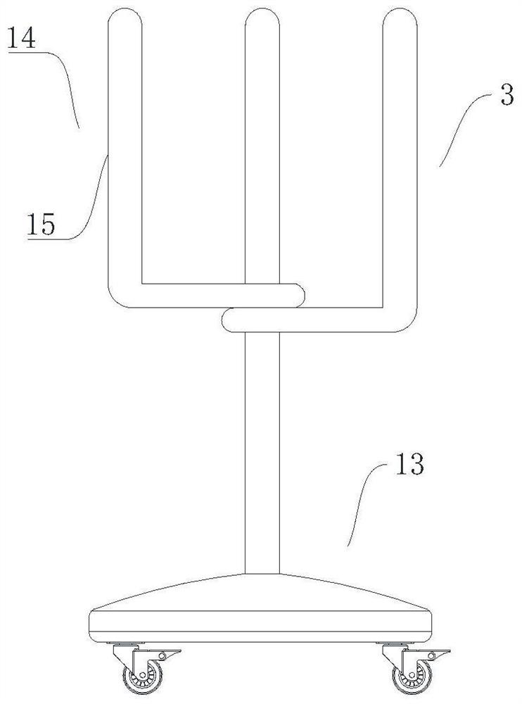
[0045] Please refer to Figure 1-Figure 6 , figure 1 Shown is a schematic structural diagram of the mobile assembly 3 in the embodiment of the present invention;

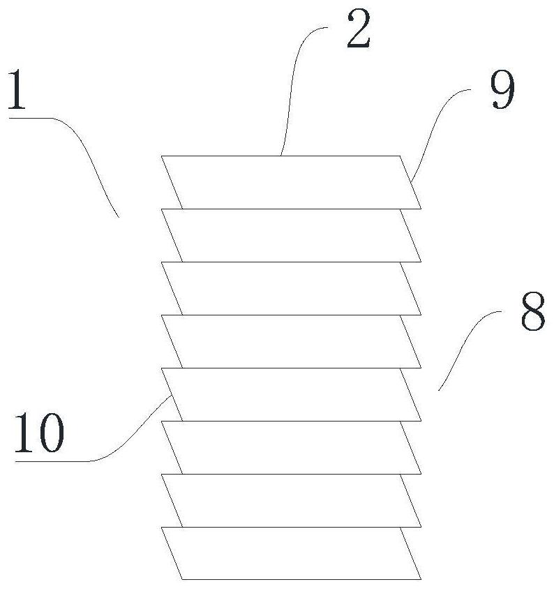
[0046] figure 2 Shown is a schematic structural view of one of the protective body 1 in the embodiment of the present invention;

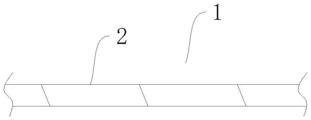
[0047] image 3 Shown is a schematic structural view of one of the protective main bodies 1 deployed in the embodiment of the present invention;

[0048] Figure 4 Shown is a schematic structural view of another protective body 1 in the embodiment of the present invention;

[0049] Figure 5 Shown is a schematic structural view of the connector in the embodiment of the present invention;

[0050] Figure 6 Shown is a cross-sectional view of the guard 2 in the embodiment of the present invention

[0051] The embodiment of the present application provides a radiological radiation protection device, which includes a protective body 1 and a mobile assembly 3 connected to each other; ...

Embodiment 2

[0070] Such as Figure 4 as shown, Figure 4 It is a structural schematic diagram of another protective body 1 in the embodiment of the present invention; in this embodiment, the above-mentioned connecting part 8 includes a spherical protrusion 11 and a spherical groove 12 connected to each other; the spherical protrusion 11 and the spherical groove 12 slide Cooperate. Such as Figure 4 As shown, that is to say, at both ends of the narrow side of a single protective piece 2, one end is provided with a spherical protrusion 11, while the other end is a spherical groove 12 provided. The block 11 snaps into the corresponding star groove; and the connection part 8 of this structure can make the protective body 1 rotate within a certain range, that is, there can be a certain gap between two adjacent protective parts 2. radians, and also does not affect the gap between the two.

[0071] In this embodiment, the moving assembly 3 includes a moving frame 13 and a mounting frame 14 c...


PUM


Abstract

The invention provides radiation medicine ray protection equipment, and relates to the technical field of medical instruments. Comprising a protection body and a moving assembly which are mutually connected. The protection main body comprises a plurality of protection parts which are connected in sequence, and the adjacent protection parts can be switched between a folding state and a paving state; the moving assembly is detachably connected with the protection main body; when the whole device is used, compared with traditional protective clothing, the trouble of inconvenient wearing can be avoided, and the X-ray detection speed is increased; secondly, compared with traditional protective cloth, the protective cloth can be prevented from being influenced by external force, and the situation that the protective cloth is lifted up accidentally, and the protective effect is greatly influenced is avoided; and compared with a protection plate used at present, the device is convenient to store and move, so that when the device is used, the whole device has higher practicability and flexibility.

Description

technical field [0001] The invention relates to the technical field of medical devices, in particular to radiation protection equipment for radiation medicine. Background technique [0002] Rays are particles or photon beams with specific energy emitted by various radionuclides, or atoms, electrons, neutrons and other particles during the energy exchange process. The common ones are x-rays, alpha rays, beta rays, gamma rays and neutron rays. [0003] Medical rays are usually X-rays. X-rays are electromagnetic waves with extremely short wavelengths and high energy. Between 0.001 and 0.1 nanometers), its photon energy is tens of thousands to hundreds of thousands of times greater than that of visible light; X-rays have high penetrating power and can pass through many substances that are opaque to visible light, such as ink paper, Timber etc. This invisible ray can cause visible fluorescence in many solid materials, sensitize photographic negatives, and ionize air. X-rays w...

Claims


Application Information

Patent Timeline
Patent Type & Authority Applications(China)
IPC IPC(8): A61B6/10
Inventor 李洁清李贞李卫国毛雪松牛菲
Owner 山东省医学科学院放射医学研究所
Learn More