Elastic pin connecting end reinforcing length-adjustable buckling-restrained brace system and mounting method
A technology of anti-buckling support and connection end, which is applied in the direction of earthquake resistance, building components, protective buildings/shelters, etc., and can solve the problem that the gap between the pin shaft and the hole wall is difficult to control accurately, the support end is prone to local bending damage, unfavorable maintenance and Replace built-in supports and other issues to ensure the quality of production and assembly installation, avoid local bending damage, and accurately predict the force characteristics
- Summary
- Abstract
- Description
- Claims
- Application Information
AI Technical Summary
Problems solved by technology
Method used
Image
Examples
specific Embodiment approach 1
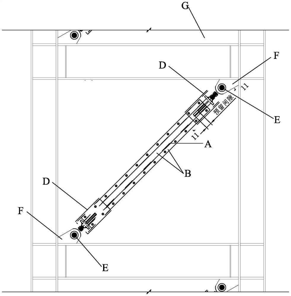
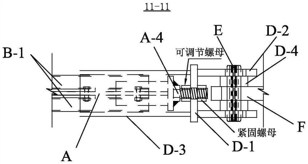
[0060] Specific implementation mode one: combine Figure 1 to Figure 26 To illustrate this embodiment, the elastic pin connection end reinforcement length adjustable anti-buckling support system of this embodiment includes a built-in support steel plate A, two constraining members B, a perforated liner C, two pin joint parts D, elastic cylindrical pins E and perforated gusset F,
[0061] The two restraint members B are the front restraint member and the rear restraint member respectively. The front restraint member and the rear restraint member are installed on the upper and lower ends of the built-in support steel plate A in the length direction, and the perforated liner C is installed on the built-in support steel plate A In the gap with the constraint member B, two pin joint parts D are respectively set on one end of the built-in supporting steel plate A in the length direction, and the pin joint part D and the gusset plate F with holes are hinged by elastic cylindrical pin...
specific Embodiment approach 2
[0075] Specific implementation mode two: combination Figure 3 to Figure 6 To illustrate this embodiment, the upper high-strength bolt A-4 and the lower high-strength bolt A-5 of this embodiment are respectively fixed and installed on the outer sides of the two square connecting plates A-3 by welding around the entire periphery of the bolt head. end face. With such arrangement, the connection method is simple and reliable, and it is convenient for force transmission. Other compositions and connections are the same as in the first embodiment.
specific Embodiment approach 3
[0076] Specific implementation mode three: combination Figure 10 to Figure 13 The present embodiment will be described. The thickness of the second perforated liner C-2 in this embodiment is less than or equal to the thickness of the first perforated liner C-1. In addition, when the second perforated liner C-2 is used alone to leave a gap in the plate thickness direction, the thickness of the first perforated liner C-1 is equal to the thickness of the steel plate support. In this way, the second opening liner C- 2 is a thin liner, which is used to adjust the gap between the constraining members B except for the first liner. Other compositions and connections are the same as those in Embodiment 1 or Embodiment 2.
[0077] The sum of the thicknesses of the first perforated liner C-1 and the second perforated liner C-2 in this embodiment should be equal to the sum of the supporting thickness of the steel plate and the gap in the plate thickness direction.
PUM
 Abstract
Description
Claims
Application Information
 - R&D
- Intellectual Property
- Life Sciences
- Materials
- Tech Scout
- Unparalleled Data Quality
- Higher Quality Content
- 60% Fewer Hallucinations
Browse by: Latest US Patents, China's latest patents, Technical Efficacy Thesaurus, Application Domain, Technology Topic, Popular Technical Reports.
© 2025 PatSnap. All rights reserved.Legal|Privacy policy|Modern Slavery Act Transparency Statement|Sitemap|About US| Contact US: help@patsnap.com


