
Motor parameter identification method and device

An identification method and a technology of motor parameters, which are applied in the direction of controlling electromechanical transmissions, controlling generators, motor generators, etc., can solve problems such as reduced identification accuracy, rotor vibration deviation, and decreased identification accuracy, so as to reduce identification errors and improve The effect of recognition accuracy and simple recognition

Active Publication Date: 2022-04-01
ZHEJIANG UNIV
View PDF11 Cites 0 Cited by
  • Summary
  • Abstract
  • Description
  • Claims
  • Application Information

AI Technical Summary

Problems solved by technology

However, due to the attraction of the permanent magnet rotor to the stator teeth and slots, the rotor will deviate after positioning. If the positioning current is increased to prevent the deviation, the magnetic circuit will be saturated and the identification accuracy will be reduced.
In addition, after the rotor is positioned, when the sinusoidal excitation is applied, the rotor may vibrate and deviate from the d-axis, resulting in a decrease in identification accuracy, and it is impossible to accurately identify the quadrature axis inductance parameter Lq

Method used


Image

  • Motor parameter identification method and device
  • Motor parameter identification method and device
  • Motor parameter identification method and device

Examples


Embodiment Construction

[0036] Various embodiments of the invention will be described in more detail below with reference to the accompanying drawings. In the various drawings, the same elements are denoted by the same or similar reference numerals. For the sake of clarity, various parts in the drawings have not been drawn to scale.

[0037] The specific implementation manners of the present invention will be further described in detail below in conjunction with the accompanying drawings and embodiments.

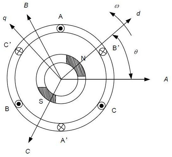
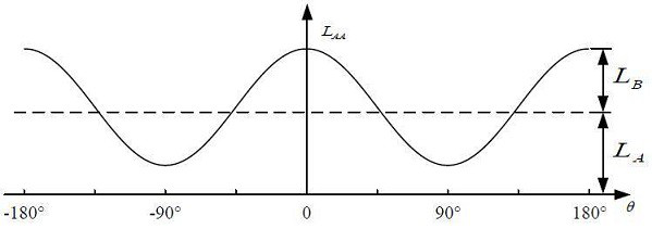
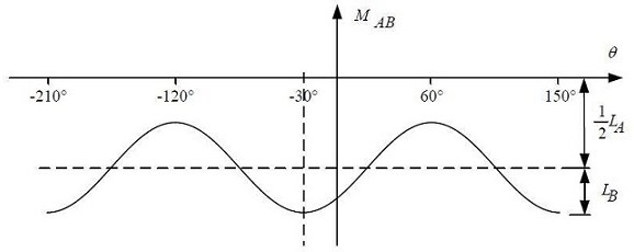
[0038] figure 1 A diagram showing the spatial relationship of the rotor poles of a permanent magnet synchronous motor; figure 2 Shows the relationship between the self-inductance parameters of any phase of the permanent magnet synchronous motor and the rotor position angle; image 3 Shows the relationship between the mutual inductance parameters between the two phases of the permanent magnet synchronous motor and the rotor position angle.

[0039] N-S is the permanent magnet of the permanent m...


PUM


Abstract

The invention discloses a motor parameter identification method, which comprises the steps of sequentially controlling an inverter to conduct any two-phase bridge arm according to a first preset conduction mode and a second preset conduction mode, applying a forward voltage pulse to a winding of a permanent magnet synchronous motor in the first preset conduction mode, and applying a reverse voltage pulse to the winding of the permanent magnet synchronous motor in the second preset conduction mode, applying a reverse voltage pulse to a winding of the permanent magnet synchronous motor; acquiring a direct current bus voltage under the forward voltage pulse, and acquiring a first current value and a second current value of a corresponding winding on a conduction bridge arm at different moments under the forward voltage pulse; and calculating a quadrature-axis inductance parameter and a direct-axis inductance parameter according to the direct-current bus voltage under the forward voltage pulse, the first current value, the second current value and the current acquisition time interval. The invention further provides a motor parameter identification device which can be used for identifying inductance parameters very simply and conveniently before the motor runs under the condition that the inductance parameters of the motor are unknown.

Description

technical field [0001] The invention relates to the technical field of motor control, in particular to a motor parameter identification method and device. Background technique [0002] Permanent magnet synchronous motor (Permanent magnet synchronous machine, PMSM) has the advantages of high power density, wide speed range, high efficiency, small size, fast response and reliable operation. It is used in household appliances, CNC machine tools, industrial robots, electric vehicles and aviation Equipment and other AC drive occasions are widely used. [0003] The motor vector control algorithm has a strong dependence on the parameters of the motor, among which the inductance is the most important parameter, which is a parameter that changes continuously with the current. Obtaining accurate inductance parameters plays a very important role in improving motor control efficiency, accurate estimation of motor speed, current loop control accuracy, and field weakening control. [00...

Claims


Application Information

Patent Timeline
Patent Type & Authority Applications(China)
IPC IPC(8): H02P21/14H02P25/024H02P27/06H02M7/5387
Inventor 徐晖黄晓艳吴美飞
Owner ZHEJIANG UNIV
Learn More