Optical receiving system based on large-mode-field single-mode fiber array

A single-mode fiber, optical receiving technology, applied in the field of free-space optical receiving systems, can solve problems such as interference signal processing, limiting system communication rate, etc., to achieve strong anti-interference ability, strong light-receiving ability, and reduce alignment requirements.

Active Publication Date: 2022-04-01
PURPLE MOUNTAIN LAB
View PDF14 Cites 0 Cited by
  • Summary
  • Abstract
  • Description
  • Claims
  • Application Information

AI Technical Summary

Problems solved by technology

Using conventional large-diameter multimode fibers will introduce too many high-order modes, which will interfere with subsequent signal processing on the one hand, and intermodal dispersion will greatly limit the communication rate of the system on the other hand.

Method used


Image

  • Optical receiving system based on large-mode-field single-mode fiber array
  • Optical receiving system based on large-mode-field single-mode fiber array
  • Optical receiving system based on large-mode-field single-mode fiber array

Examples


Embodiment 1

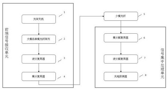
[0027] as attached figure 1 As shown, an optical receiving system based on a large mode field single-mode fiber array includes a front-end signal receiving unit and a centralized signal processing unit. The front-end signal receiving unit is used to receive a spatial optical signal and process the spatial optical signal into a wave For the optical signal of division and mode division multiplexing, the centralized signal processing unit is used to demultiplex the optical signal of wavelength division and mode division multiplexing, and then convert the optical signal. The front-end signal receiving unit and the centralized signal processing unit perform optical signal transmission through the few-mode optical fiber 5 .

[0028] The front-end signal receiving unit includes an optical antenna 1, a large mode field single-mode fiber array 2, a wavelength division multiplexer 3 and a mode division multiplexer 4, and the centralized signal processing unit includes a mode division mu...

Embodiment 2

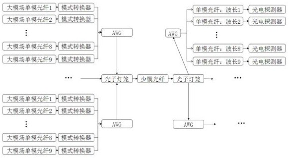
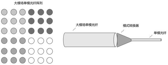
[0040] as attached figure 2 And attached image 3 As shown, in the optical receiving system based on a large mode field single-mode fiber array in this embodiment, in the front-end signal receiving unit, the optical antenna 1 receives the spatial optical signal, and is used for converging the spatial optical signal and then transmitting it. The mode field single-mode fiber array 2 adopts a 6*6 matrix mode and a large mode field single-mode fiber array, and each large mode field single-mode fiber independently receives the converged spatial optical signal, because the large mode field single-mode fiber itself The mode range is limited, and the large mode field single-mode fiber array 2 is divided into 9×4 partitions, that is, the 6*6 matrix is ​​divided into four 3*3 sub-arrays, and the large-mode field single-mode fiber array is divided into 4 sub-arrays, namely M =4, each sub-array includes 9 large-mode-field single-mode fibers, that is, 3*3 sub-arrays, N=9, according to th...


PUM


Abstract

The invention discloses an optical receiving system based on a large-mode-field single-mode fiber array, which comprises a front-end signal receiving unit and a signal centralized processing unit, and is characterized in that the front-end signal receiving unit is used for receiving spatial optical signals and processing the spatial optical signals into wavelength division multiplexing and mode division multiplexing optical signals; the signal centralized processing unit is used for carrying out demultiplexing on the optical signals subjected to wavelength division multiplexing and mode division multiplexing and then carrying out photoelectric signal conversion; the front-end signal receiving unit comprises a large-mode-field single-mode optical fiber array, and the large-mode-field single-mode optical fiber array is used for receiving spatial optical signals. The large-mode-field single-mode optical fiber array is adopted to replace a single-mode optical fiber used in traditional space optical communication, and due to the characteristics of a large mode field and a single mode, the large-mode-field single-mode optical fiber array is high in anti-interference capacity, free of high-order-mode optical signals, larger in usable angle and coverage range, higher in light receiving capacity when receiving space optical signals, and capable of improving the light receiving efficiency. And the alignment requirement of a receiving system is reduced.

Description

technical field [0001] The invention relates to a free space optical receiving system, in particular to an optical receiving system based on a large mode field single-mode fiber array. Background technique [0002] With the rise of 5G wireless communication and the demand of B5G (super 5th generation mobile communication system) / 6G for high-speed wireless communication, wireless optical communication with high transmission rate has attracted more and more attention. In wireless optical communication systems, whether it is satellite-to-ground laser communication at ultra-long distances, free-space optical communication at medium-to-long distances, or indoor infrared and visible light communication at short distances, optical fibers have gradually become the receiving end due to their flexible and high-speed characteristics. At the same time, in order to further increase the system transmission rate and communication capacity, the use of optical fiber arrays is becoming more a...

Claims


Application Information

Patent Timeline
Patent Type & Authority Applications(China)
IPC IPC(8): H04B10/60H04J14/02H04J14/04
CPCY02D30/70
Inventor 朱世程曹珂张启王家恒高西奇孙晨
Owner PURPLE MOUNTAIN LAB
Why Eureka
Try Eureka