Narrow-gap MAG/MIG automatic horizontal position welding device and method based on welding wire plastic deformation

A technology of plastic deformation and narrow gap, applied in welding equipment, welding accessories, arc welding equipment, etc., can solve the problems of large welding residual stress and residual deformation, high labor intensity of welding operators, complex hardware and software systems, etc. Welding residual stress and residual deformation, uniform fusion, reliable, more controllable and stable, and the effect of improving welding productivity

Pending Publication Date: 2022-04-05
武汉纳瑞格智能设备有限公司
View PDF7 Cites 2 Cited by
  • Summary
  • Abstract
  • Description
  • Claims
  • Application Information

AI Technical Summary

Problems solved by technology

[0003] K-type groove MAG / MIG automatic horizontal welding is the most traditional automatic horizontal welding method. Its main limitations are the large area of ​​the welding groove, the large consumption of welding wire, electric energy, shielding gas and working hours, and the large welding residual stress and residual deformation. Low welding productivity and high welding production costs
Narrow gap groove MAG / MIG automatic horizontal welding is an upgraded technology of K-type groove MAG / MIG automatic horizontal welding, which can basically overcome all the limitations of K-type groove MAG / MIG automatic horizontal welding; The fusion control technology of the side wall of the upper and lower grooves still has the following main limitations: the method of manual real-time observation of the arc action position and real-time manual adjustment of the arc action position, the labor intensity of welding operators is high, and the reliability is low; the use of two-dimensional laser real-time tracking technology , image processing, real-time tracking technology, and other closed-loop control tracking technologies to solve the problem of accurate and reliable arc action position. The software and hardware system of various welding seam trajectory adaptive tracking technologies, although it has intelligent functions, greatly reduces human labor. Strength, which improves the stability and reliability of welding quality, but basically has the general limitations of complex software and hardware systems, poor anti-interference ability, and high equipment cost
Due to the low productivity of narrow gap pulse TIG automatic horizontal welding, there are relatively few production applications

Method used


Image

  • Narrow-gap MAG/MIG automatic horizontal position welding device and method based on welding wire plastic deformation
  • Narrow-gap MAG/MIG automatic horizontal position welding device and method based on welding wire plastic deformation
  • Narrow-gap MAG/MIG automatic horizontal position welding device and method based on welding wire plastic deformation

Examples


Embodiment 1

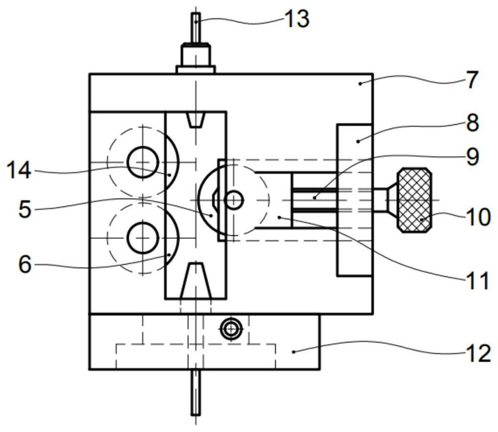
[0033] Such as Figure 1-4As shown, the wire straightening mechanism that can rotate along the circumference of the welding wire consists of a wire straightening mechanism body 7, a first fulcrum roller 6, a second fulcrum roller 14, a wire straightening roller 5, a wire straightening roller seat 11, a screw 9, Nut seat 8, knob 10, and swivel seat 12 form. The center of rotation of the first fulcrum roller 6 and the second fulcrum roller 14 is parallel to the axis of the welding wire 13, and the center distance between the two fulcrum rollers is greater than the diameter of a fulcrum roller; One-half of the center distance. The upper and lower sides of the straightening roller seat 11 are processed into boss-shaped guide rails, and the corresponding positions where the straightening roller seat 11 is installed in the straightening mechanism body 7 are processed into guide rail grooves, and the straightening roller seat 11 is pushed by the rear screw 9 Next, the wire straight...

Embodiment 2

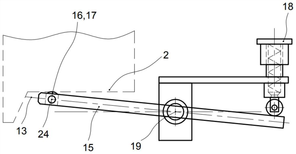
[0039] Such as Figure 5-6 As shown, embodiment 2 is the method for applying the automatic horizontal welding device in embodiment 1 to carry out automatic horizontal welding, which specifically includes the following steps:

[0040] S1. Respectively deflect the front plate type narrow gap MAG / MIG welding torch and the rear plate type narrow gap MAG / MIG welding torch to make it into a scissors shape;

[0041] S2. The cladding method of two layers per layer is adopted; the arc of the front pass acts on the sharp corner of the lower wall of the groove of the weldment, and the arc of the rear pass acts on the sharp corner of the upper wall of the groove of the weldment;

[0042] S3. After the molten pool of the front bead is solidified, the rear weld bead is welded when it is still in the high temperature range of 700°C to 800°C; with the backward tilting method, the arc acts on the fusion zone in front of the molten pool;

[0043] S4. The front plate type narrow gap MAG / MIG wel...

Embodiment 3

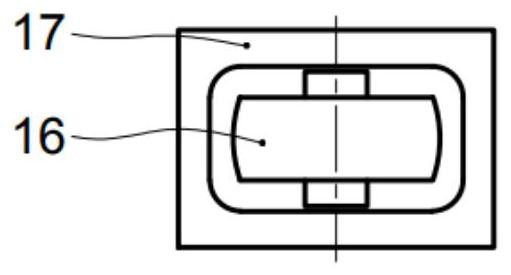
[0048] In Example 3, the master roll 16 is made of alumina ceramics, with a total thickness of 8 mm, a roll diameter of 6 mm, and a roll shaft diameter of 3 mm. Other structures are the same as in Example 1.


PUM


Abstract

The invention discloses a narrow-gap MAG / MIG automatic horizontal position welding device based on welding wire plastic deformation, which comprises a front plate type narrow-gap MAG / MIG welding gun and a rear plate type narrow-gap MAG / MIG welding gun, and wire straightening mechanisms are respectively arranged at the adjacent rear parts of wire feeding mechanisms of the front plate type narrow-gap MAG / MIG welding gun and the rear plate type narrow-gap MAG / MIG welding gun; and the front plate type narrow-gap MAG / MIG welding gun and the rear plate type narrow-gap MAG / MIG welding gun are respectively provided with a floating mechanism, an elastic force applying mechanism and a rolling profiling mechanism. A stepless wire straightening method for any position in the circumferential direction of the welding wire is used for adjusting the pointing and acting positions of the welding wire and the electric arc, meanwhile, simultaneous operation of double guns, double wires and double electric arcs is combined, the mechanical self-adaptive tracking technology of elastic floating profiling tracking is adopted, the welding productivity is greatly improved, and meanwhile the welding production cost is greatly reduced.

Description

technical field [0001] The invention relates to a narrow-gap MAG / MIG automatic horizontal welding device and method for controlling the correct action position of a welding wire and an arc through plastic deformation of the welding wire, and belongs to the field of welding technology. Background technique [0002] In equipment manufacturing and installation engineering, the application forms of welding operations in the horizontal welding position are extremely wide, especially the automatic horizontal welding application based on the melting arc welding technology method can be found everywhere. The existing automatic horizontal welding technology mainly includes the following five methods: one is K-type groove MAG / MIG automatic horizontal welding; the other is narrow gap groove MAG / MIG automatic horizontal welding; the third is traditional groove submerged arc automatic horizontal welding; The fourth is narrow gap groove submerged arc horizontal welding; the fifth is narro...

Claims


Application Information

Patent Timeline
Patent Type & Authority Applications(China)
IPC IPC(8): B23K9/173B23K9/133B23K9/32
Inventor 张富巨张瑞李小康
Owner 武汉纳瑞格智能设备有限公司
Why Eureka
Try Eureka