Performance gain structure of transmission coil and design method thereof

A transmission coil, performance technology, applied in the direction of transformer/inductor coil/winding/connection, electrical components, circuit devices, etc., can solve the problem of large area of ​​transmission coil contacting PCB substrate, increase the transmission efficiency of substrate coil, and compress enameled wire Insulation skin and other issues, to achieve the effect of flexible design, reduce tangent loss, and improve heat dissipation performance

Pending Publication Date: 2022-04-05
西安电掣风云智能科技有限公司
View PDF2 Cites 0 Cited by
  • Summary
  • Abstract
  • Description
  • Claims
  • Application Information

AI Technical Summary

Problems solved by technology

In practical applications, there are the following problems: First, the contact area of ​​the transmission coil with the PCB substrate is large, which increases the influence of the "tangent loss" (DF value) of the substrate on the transmission efficiency of the coil, so under the uniform design distance, the coupling coefficient of the coil will decrease by a few percentage points
The design of the flat groove is only suitable for low frequency, not suitable for high frequency
Moreover, the coil is sandwiched between the two sides, which is likely to compress the insulation sheath of the enameled wire or Litz wire, causing system failure

Method used


Image

  • Performance gain structure of transmission coil and design method thereof
  • Performance gain structure of transmission coil and design method thereof
  • Performance gain structure of transmission coil and design method thereof

Examples


Embodiment 1

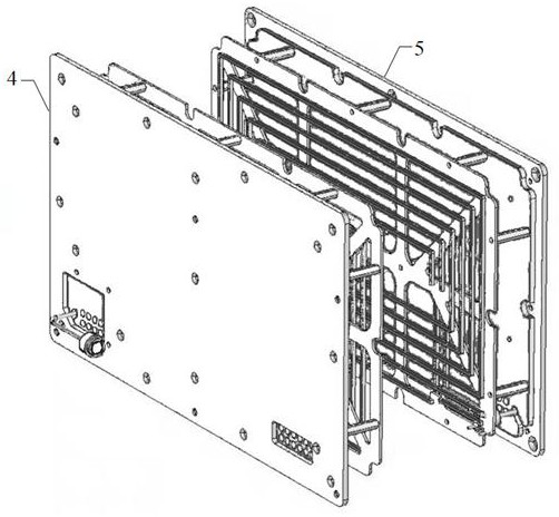
[0036] A performance gain structure for a transmission coil such as figure 1 As shown, the receiving module 5 has the same structure as the transmitting module 4 and is arranged symmetrically.

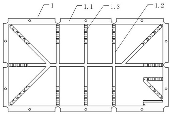
[0037] like Figure 2-4 As shown, the receiving module 5 includes an insulating substrate frame 1, on which the coil 2 is wound, and the substrate frame 1 includes a frame 1.1 hollowed out inside, and a plurality of ribs 1.2 for supporting the coil 2 are arranged inside the frame 1.1. The ribs 1.2 are perpendicular to the winding direction of the coil 2. The position where the coil 2 contacts the substrate skeleton 1 is provided with a fixed structure 1.3. The side of the substrate skeleton 1 far away from the coil 2 is equipped with a magnetic partition 3, and the magnetic partition 3 is evenly provided with multiple Holes 3.1.

[0038] The magnetic separator 3 is parallel to the coil 2 to enhance the gain of the magnetic field in the transmission direction, and the parallelism of t...

Embodiment 2

[0050] A method for designing a performance gain structure of a transmission coil, specifically performed according to the following steps:

[0051] Step 1: Engraving the outline corresponding to coil 2 on the copper skin of the existing PCB substrate (or copper clad laminate);

[0052] Step 2: Keep the ribs and bones of the PCB substrate to support the coil 2, and hollow out the rest of the area;

[0053] Step 3: The copper skin of the ribs is used as the supporting solder joint of the coil 2;

[0054] Step 4: Fully immerse silver on the copper surface to prevent copper oxidation and improve conductivity.

[0055] The present invention has the following advantages:

[0056] 1. Improve the heat dissipation performance of the coil while improving the coupling transmission efficiency of the coil; according to the simulation results of the embodiment of the present invention and the existing unprocessed circuit board comparison, the substrate skeleton 1 of the present invention...


PUM


Abstract

The invention discloses a performance gain structure of a transmission coil and a design method thereof, a receiving module and a transmitting module have the same structure and are symmetrically arranged, the receiving module comprises a substrate skeleton made of an insulating material, a coil is wound on the substrate skeleton, only a part for supporting the coil is reserved on the substrate skeleton, the rest part of the substrate skeleton is hollowed out, and the receiving module is connected with the transmitting module. A magnetic partition plate is installed on the side, away from the coil, of the substrate framework, and a plurality of holes are evenly formed in the magnetic partition plate. The coupling transmission efficiency of the coil is improved, the heat dissipation performance of the coil is improved, and the design flexibility and flexibility of the coil module are enhanced.

Description

technical field [0001] The invention belongs to the field of wireless electromagnetic and energy technology, and relates to a performance gain structure of a transmission coil and a design method thereof. Background technique [0002] Most of the existing transmission coils are wound with conductors into coils and then placed on circuit boards or magnetic core boards. Integrated row or high-frequency coils are almost all made directly from copper-clad circuit boards. In practical applications, there are the following problems: First, the contact area of ​​the transmission coil to the PCB substrate is large, which increases the influence of the substrate "angular tangent loss" (DF value) on the transmission efficiency of the coil, so under the uniform design distance, the coupling coefficient of the coil will drop by a few percentage points. Second, the problem of heat generation; most of the substrates are made of non-thermally conductive plastics. If the copper clad lamin...

Claims


Application Information

Patent Timeline
Patent Type & Authority Applications(China)
IPC IPC(8): H02J50/00H02J50/10H02J50/70H01F27/30H01F27/28H01F27/08
Inventor 李谦
Owner 西安电掣风云智能科技有限公司
Why Eureka
Try Eureka