
Short-term Power Prediction Method of Photovoltaic Power Plant Based on Lidar Cloud Image Detection

A laser radar, photovoltaic power station technology, applied in measurement devices, re-radiation of electromagnetic waves, radio wave measurement systems, etc., can solve the problems that manual observation cannot achieve accurate judgment and prediction, complex data processing process, and prolonged debugging period, etc. Achieve the effect of low investment and construction cost, wide application range and light weight

Active Publication Date: 2022-06-07
南京鼐云科技股份有限公司
View PDF0 Cites 0 Cited by
  • Summary
  • Abstract
  • Description
  • Claims
  • Application Information

AI Technical Summary

Problems solved by technology

At present, cloud monitoring methods mainly include manual observation, satellite imaging cloud image recognition, and ground-based all-sky image recognition, but manual observation cannot accurately determine and predict in complex situations and large-scale environments, and the efficiency is low; satellite imaging cloud image recognition needs With the help of satellite images, the cost is extremely high, and most photovoltaic power plants cannot realize it; ground-based all-sky image recognition requires a large number of ground-based all-sky camera CCD equipment around the photovoltaic power plant, which is too expensive, and because of the need for cloud image recognition, it takes a long time Collect images for recognition algorithm training, and the sun halo and non-empty environment imaging interference involved in the images lead to complex data processing, resulting in large prediction errors. The prediction models between different photovoltaic farms are relatively independent, and photovoltaic farms are used The commissioning period is extended. For the initial use of photovoltaic power plants, the lack of atmospheric climate and historical data of photovoltaic power generation may result in prolonged construction periods and increased costs.

Method used


Image

  • Short-term Power Prediction Method of Photovoltaic Power Plant Based on Lidar Cloud Image Detection
  • Short-term Power Prediction Method of Photovoltaic Power Plant Based on Lidar Cloud Image Detection
  • Short-term Power Prediction Method of Photovoltaic Power Plant Based on Lidar Cloud Image Detection

Examples


Embodiment Construction

[0035] Below in conjunction with the accompanying drawings and specific embodiments, the present invention will be further clarified. It should be understood that these embodiments are only used to illustrate the present invention and not to limit the scope of the present invention. Modifications of equivalent forms all fall within the scope defined by the appended claims of this application.

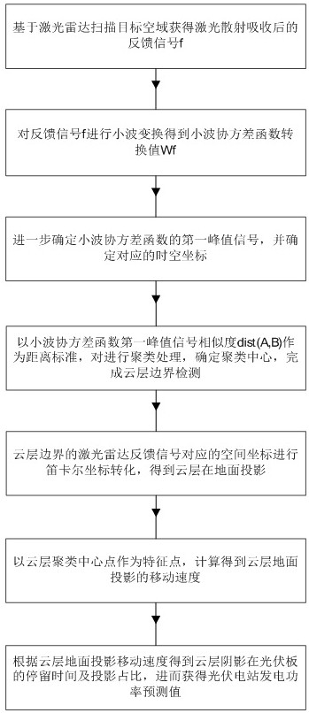
[0036] like figure 1 As shown, the specific steps of the short-term power generation power prediction method of a photovoltaic power station based on lidar cloud image detection of the present invention are as follows:

[0037]Step S1, using the scattering and absorption effect of atmospheric gas molecules and aerosols on laser light, using ground-based lidar to detect and scan the airspace near the photovoltaic power station to obtain a feedback signal after laser scattering and absorption in the target airspace , the feedback signals are different spatial coordinate points The gra...


PUM


Abstract

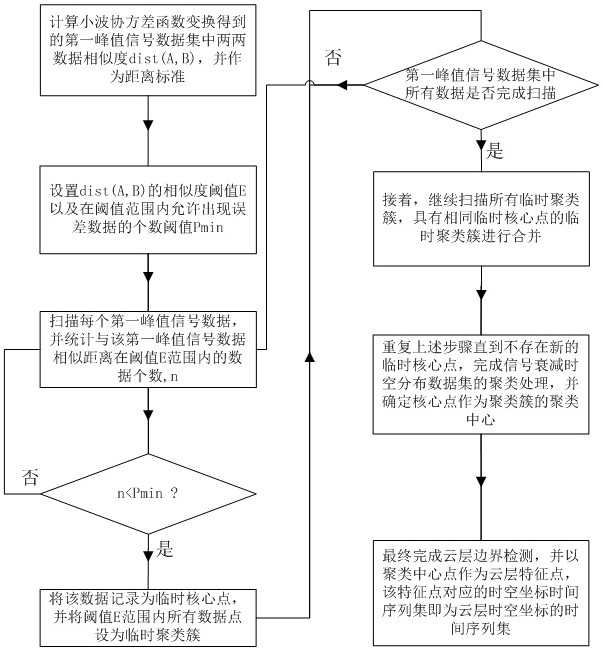
The invention discloses a method for predicting short-term power generation power of a photovoltaic power station based on laser radar cloud image detection. The ground-based laser radar is used to detect and scan the airspace near the photovoltaic power station to obtain the feedback echo signal after laser scattering and absorption in the target airspace, and to continuously detect in real time according to the clustering algorithm Estimate the atmospheric cloud information, so as to predict the proportion and residence time of the cloud boundary in the solar panel of the target photovoltaic power station, and realize the short-term prediction of the power generation of the photovoltaic power station. The device of the present invention has the characteristics of small volume, light weight, continuous real-time observation, and high resolution. Compared with the gradient method GARD and the standardized deviation method STD, it has the same consistency. Effectively avoid miscalculation and reduce short-term generating power prediction error rate.

Description

technical field [0001] The invention belongs to the technical field of laser radar imaging identification, and in particular relates to a short-term power generation power prediction method of a photovoltaic power station based on laser radar cloud image detection. Background technique [0002] Due to the depletion and depletion of petrochemical energy and its pollution impact on the environment, solar photovoltaic power generation plays an increasingly important role in the global energy system due to its clean and sustainable advantages. With the continuous increase in the scale of investment and construction of my country's photovoltaic industry, the advantages and scale effects of photovoltaic power generation systems are gradually reflected, especially in the high-altitude, high-north latitude areas with the advantages of high altitude, long sunshine, sparsely populated and unobstructed, etc. Sustained rapid development, as a high-quality energy source, it usually adopts...

Claims


Application Information

Patent Timeline
Patent Type & Authority Patents(China)
IPC IPC(8): G01S7/48G01S17/95G06K9/00G06K9/62
CPCY02A90/10
Inventor 周鹏章旺吴斌
Owner 南京鼐云科技股份有限公司
Learn More