Auxiliary motion device, driving system and control method

A motion device and driving device technology, applied in the fields of auxiliary motion devices, driving systems and control, can solve the problems of low motion accuracy, inability to use in nuclear magnetic environment, complex structure of motion devices, etc., and achieve the effect of increasing accuracy

Pending Publication Date: 2022-04-12
HANGZHOU GENLIGHT MEDTECH CO LTD
View PDF0 Cites 1 Cited by
  • Summary
  • Abstract
  • Description
  • Claims
  • Application Information

AI Technical Summary

Problems solved by technology

[0006] In view of the above analysis, the present invention aims to provide an auxiliary movement device, a drive system and a control method to solve the problem of complex structure, low movement precision, inaccurate orientation control of surgical instruments and inability to operate in a nuclear magnetic environment in the prior art. problem of use

Method used


Image

  • Auxiliary motion device, driving system and control method
  • Auxiliary motion device, driving system and control method
  • Auxiliary motion device, driving system and control method

Examples


Embodiment 1

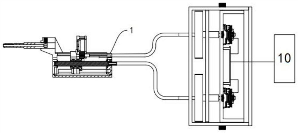
[0065] The present invention proposes an auxiliary movement device including a frame 1, a movement assembly and a drive assembly, the movement assembly and the drive assembly are provided separately, and there is a certain distance between the movement assembly and the drive assembly during actual use. The setting distance of the driving assembly is that the driving assembly is set away from the NMR main body or the magnetic resonance chamber. Firstly, the influence of the driving assembly on the magnetic resonance imaging and temperature measurement technology is avoided, and the second is to reduce the weight of the moving assembly, so that the moving assembly The volume and weight of the movement components are reduced to the minimum, so that the movement components can be fixedly connected with the skull nails without additional fixing devices; at the same time, the reduction of the weight of the movement components can increase its stability, so that it can be used during m...

Embodiment 2

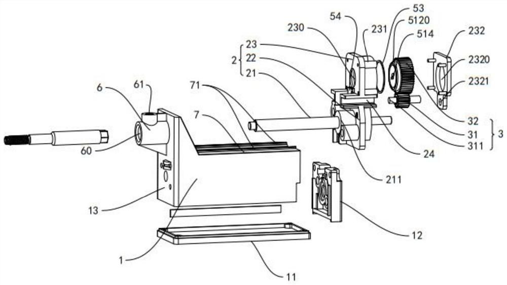
[0076] see again Figure 2A to Figure 2C , Figure 3A to Figure 3B , Figure 4A to Figure 4B , Another specific embodiment 2 of the present invention differs from embodiment 1 in that, in order to make the movement of the rotary motion assembly 3 more stable and precise, the present embodiment 2 applies the linear motion assembly 2 and the rotary The cooperation mode between the motion components 3 has been further optimized.

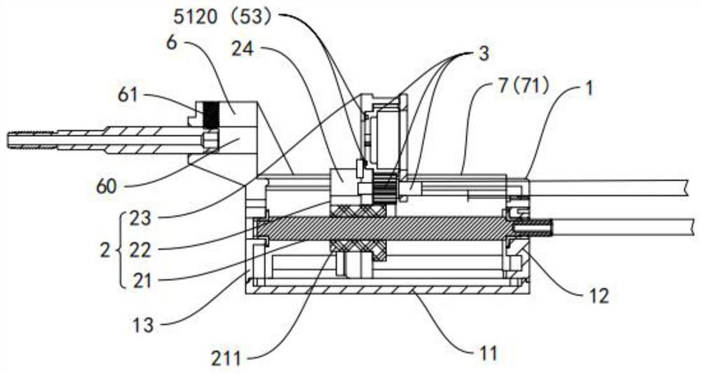
[0077] The ring neck 231 includes a first ring neck 2311 and a second ring neck 2312 , and the connection between the first ring neck 2311 and the second ring neck 2312 forms a stepped shape. Correspondingly, the side of the driven wheel 32 that conflicts with the linear driven moving part 23 has a stepped abutting surface that is adapted to the ring neck 231 . That is to say, the ring neck 231 (or the linear driven moving part 23) and the driven wheel 32 are installed together through at least one step surface, and the ring neck 231 (or the linear d...

Embodiment 3

[0087] Further, as Figures 5B-5CAs shown, the driven wheel 32 is provided with a fiber catheter fixing part inside, and the fiber catheter fixing part includes a fiber catheter holder 51 and a fiber catheter fixing part 52, and the fiber catheter fixing part 51 and the fiber catheter fixing part 52 are detachable For mating connection, the optical fiber conduit holder 51 is fixedly fitted inside the driven wheel 32 .

[0088] Specifically, the optical fiber catheter fixer 51 is a stepped cavity structure, and the cavity structure includes a first cavity 511 and a second cavity 512 . The first concave cavity 511 and the second concave cavity 512 are both cylindrical concave cavity structures, they are coaxially arranged and adjacent to and communicate with each other, and the diameter of the first concave cavity 511 is larger than that of the second concave cavity 512 The diameter of the two adjacent to form a right-angle boss 513.

[0089] Further, a positioning groove 514 ...


PUM


Abstract

The invention relates to an auxiliary movement device, a driving system and a control method, and belongs to the technical field of ablation operation devices. An auxiliary movement device comprises a rack, a movement assembly and a driving assembly. The motion assembly is arranged on the rack, and the motion assembly is driven by the driving assembly to do linear and / or rotary motion; the driving assembly comprises a manual driving part and a full-automatic driving part; the manual driving part is used for achieving manual control over the movement assembly. The full-automatic driving part is used for achieving full-automatic control over the movement assembly. According to the invention, synchronous linear motion and rotary motion of the optical fiber conduit are realized, and the control precision of the linear displacement and the rotary angle is improved through the engagement of the lead screw and the gear; the driving assembly is provided with double driving sources, so that manual adjustment of the optical fiber conduit can be realized, and full-automatic adjustment of the optical fiber conduit can also be realized.

Description

[0001] The invention relates to the technical field of medical equipment, in particular to an auxiliary exercise device, a drive system and a control method. Background technique [0002] Medical robotics is a new interdisciplinary research field integrating medicine, biomechanics, mechanics, mechanical mechanics, materials science, computer graphics, computer vision, mathematical analysis, robotics and many other disciplines. It is currently a research hotspot in the field of robotics at home and abroad. . The most commonly used medical robot in the field of neurosurgery is also called surgical robot. In the surgical robot system, auxiliary robots account for nearly 17% of surgical operations and become one of the commonly used auxiliary equipment in daily surgical operations. With the continuous development of technology, surgical robots will develop toward miniaturization, specialization, low cost, intelligence, and automation, and will lead minimally invasive surgery into ...

Claims


Application Information

Patent Timeline
Patent Type & Authority Applications(China)
IPC IPC(8): A61B18/22A61B34/35
CPCA61B34/35A61B18/22
Inventor 夏良道金慧杰史鼎盛廖响亮
Owner HANGZHOU GENLIGHT MEDTECH CO LTD
Why Eureka
Try Eureka