
Stable machining method for thin-wall edge strip inclined end face structure

A technology of inclined end face and processing method, which is applied in the fields of metal cutting processing and numerical control processing of aeronautical structural parts, can solve the problems of poor stability and low efficiency, and achieve the effect of improving processing stability, simple processing steps, and eliminating bullet knives.

Pending Publication Date: 2022-04-12
CHENGDU AIRCRAFT INDUSTRY GROUP
View PDF6 Cites 0 Cited by
  • Summary
  • Abstract
  • Description
  • Claims
  • Application Information

AI Technical Summary

Problems solved by technology

[0004] The purpose of the invention of the present invention is to propose a processing method for the inclined end surface structure of the thin-walled edge in view of the defects of poor stability and low efficiency in the existing processing method of the inclined end surface structure of the thin-walled edge; the processing method of the present invention can be used in the processing process The inclined end face structure of the thin-walled edge can be processed quickly and stably, avoiding processing chatter, eliminating the hidden dangers of knife snapping, broaching, and clamping, and greatly reducing the workload of the fitter for grinding, thereby significantly improving production efficiency

Method used


Image

  • Stable machining method for thin-wall edge strip inclined end face structure
  • Stable machining method for thin-wall edge strip inclined end face structure
  • Stable machining method for thin-wall edge strip inclined end face structure

Examples


Embodiment 1

[0034] A processing method of a thin-walled edge strip inclined end surface structure ( Figure 5 ), including the following steps:

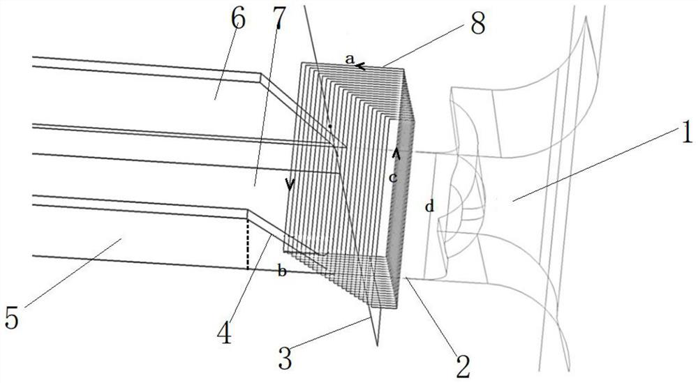
[0035] (1) The bottom surface of the web of the cylindrical end mill perpendicular to the thin-walled edge is cut along the design contour of the inclined end face at a fixed axis ( figure 2 ), until there is a 0.5mm thick connection allowance between the bottom surface of the web and the remaining blank, stop the fixed-axis cutting; among them, when the fixed-axis cutting is processed, the cutting depth of each layer is 0.3mm; Climb milling (machine speed S=20000r / min, fixed-axis cutting feed rate F=8000mm / min); the horizontal width a of the fixed-axis cutting track is set to 39mm; the maximum longitudinal width of the fixed-axis cutting track is 47mm;

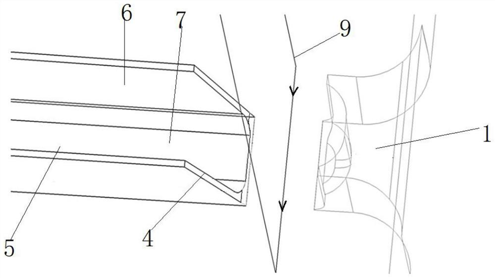
[0036] (2) Mill the cylindrical end mill perpendicular to the bottom surface of the thin-walled edge web along the sloped end face design contour in one cut (the feed speed of the milling lin...

Embodiment 2

[0039] A processing method for the inclined end surface structure of a thin-walled edge strip, comprising the following steps:

[0040] (1) The cylindrical end mill is perpendicular to the bottom surface of the web of the thin-walled edge, and the fixed axis is cut along the design contour of the inclined end face until there is a 0.8mm thick connection allowance between the bottom surface of the web and the blank, and the fixed axis is stopped. Cutting (machine tool speed S=20000r / min, fixed-axis cutting feed speed F=8000mm / min); among them, during fixed-axis cutting processing, the cutting depth of each layer is 0.2mm; the motion trajectory is one-way down milling ;The horizontal width a of the fixed-axis line cutting track is set to 43mm; the maximum longitudinal width of the fixed-axis line cutting track is 52mm;

[0041] (2) Mill the cylindrical end mill perpendicular to the bottom surface of the thin-walled edge web along the design contour of the inclined end face in on...

experiment example

[0046] The inclined end face structures of thin-walled edge strips were processed by the processing methods in Examples 1-2 of the present invention and Comparative Example 1, respectively, and 20 pieces were processed in each group, and then the numerical control machining time of the inclined end face, the grinding time of fitters and the processing quality of the parts were counted. The results as follows:

[0047] serial number Average time of CNC machining (min) Average time of fitter grinding (min) The number of failures of the NC machining bullet knife Fitter repair file size failure times Pass rate(%) Example 1 1.3 2 0 0 100 Example 2 1.9 2.5 0 0 100 Comparative Example 1 1.1 6 6 1 65

[0048] Through the comparison of the experimental results, it can be seen that using the processing method of the present invention to process the inclined end face structure of the thin-walled edge strip of the aluminum alloy can eff...


PUM

PropertyMeasurementUnit
Side wall thicknessaaaaaaaaaa

Abstract

The invention relates to a stable processing method for an inclined end face structure of a thin-wall edge strip, which comprises the following steps of: (1) performing fixed-axis line cutting on a cylindrical end mill vertical to the bottom surface of a web plate of the thin-wall edge strip along the design outline of the inclined end face until a connection allowance of 0.3-0.8 mm thick is left between the bottom surface of the web plate and a blank excess material, and stopping fixed-axis line cutting; (2) a cylindrical end mill is perpendicular to the bottom face of the thin-wall edge strip web plate, connection allowance is milled off along the inclined end face design contour, and a rough machining inclined end face structure is obtained; and (3) polishing the primarily-machined inclined end face structure to obtain the thin-wall edge strip inclined end face structure. According to the machining method, the inclined end face structure of the thin-wall edge strip can be rapidly and stably machined in the machining process, machining chatter is reduced, the hidden danger of tool bouncing, tool broaching and tool clamping is eliminated, the grinding workload of bench workers is greatly reduced, and therefore the production efficiency is remarkably improved.

Description

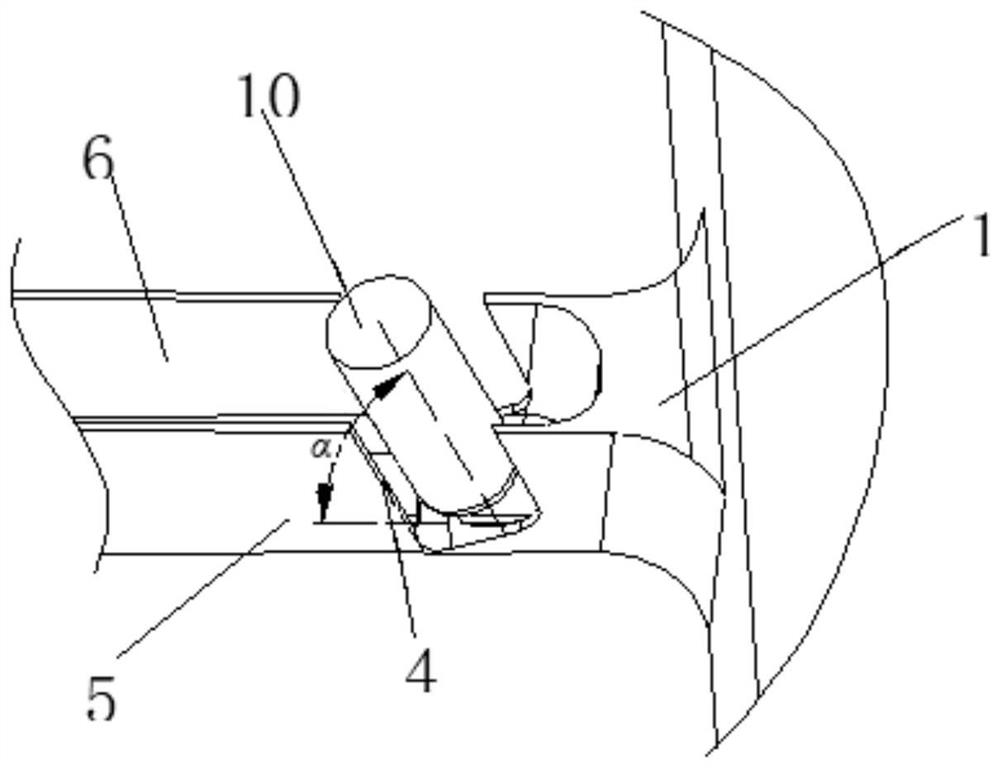
technical field [0001] The invention relates to the field of metal cutting processing, in particular to the field of numerical control processing of aeronautical structural parts, in particular to a processing method of a thin-walled edge strip inclined end surface structure. Background technique [0002] Due to the design and assembly requirements of wing spar parts (thin-walled edge strips), it is usually necessary to process the end face of such parts into an inclined end face structure; and in order to control the weight of the parts, such parts often have high sidewall height and thin wall thickness. , the characteristics of low stiffness; therefore, it is usually difficult to process the inclined end face structure of such parts. [0003] When traditional machining methods are used to process the inclined end surface structure of such thin-walled edge strips of wing spar, the end surface is milled with a longer tool swing angle (such as figure 1 shown), resulting in e...

Claims


Application Information

Patent Timeline
IPC IPC(8): B23P15/00
Inventor 王元军王丰张利翟立恒曹泽平陈莉蒙邹鹏袁田
Owner CHENGDU AIRCRAFT INDUSTRY GROUP
Learn More