Coating drying room waste gas treatment system and treatment method

A technology for waste gas treatment and drying room, which is applied in the field of waste gas treatment in paint drying room and waste gas treatment system in paint drying room

Pending Publication Date: 2022-04-12
ZHUHAI DINGLI PACKAGING PROD
View PDF0 Cites 0 Cited by
  • Summary
  • Abstract
  • Description
  • Claims
  • Application Information

AI Technical Summary

Problems solved by technology

[0004] In order to overcome the existing technical defects, the object of the present invention is to provide a paint drying room exhaust gas treatment system and method to solve the above technical problems

Method used


Image

  • Coating drying room waste gas treatment system and treatment method
  • Coating drying room waste gas treatment system and treatment method
  • Coating drying room waste gas treatment system and treatment method

Examples


Embodiment 1

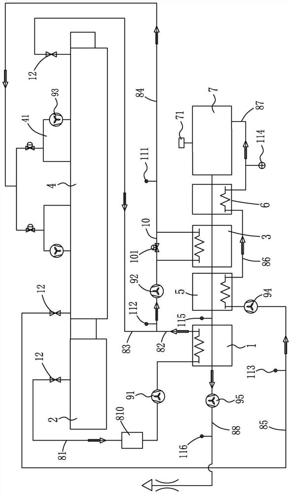
[0039] refer to figure 1 As shown, a paint drying room exhaust gas treatment system provided by the present invention includes: a first heat exchanger 1, a coating room 2, a second heat exchanger 3, a drying and curing room 4, a preheater 5, a third Heat exchanger 6, incinerator 7, connecting pipeline 10 and main control device.

[0040] The exit of the coating room 2 corresponds to the entrance of the drying and curing room 4. After the product is sprayed in the coating room 2, it is transported to the drying and curing room 4 through the conveying line for drying treatment.

[0041] The first heat exchanger 1 is connected with the painting room 2 through the first pipeline 81, the first fan 91 and the air filter 810 are connected on the first pipeline 81, and the first fan 91 is used to pump the exhaust gas from the painting room 2 to the second A heat exchanger 1 for internal heating.

[0042] The second heat exchanger 3 is connected with the first heat exchanger 1 through ...

Embodiment 2

[0061] refer to figure 1 As shown, a kind of paint drying room exhaust gas treatment method provided by the invention comprises the following steps:

[0062] The first heat exchanger 1 is connected to the painting booth 2 through the first pipeline 81, the first fan 91 and the air filter 810 are connected to the first pipeline 81, and the exhaust gas in the coating booth 2 is pumped to the The inside of the first heat exchanger 1 is heated, and the impurities in the exhaust gas are filtered through the air filter 810 .

[0063] The first heat exchanger 1 is connected with the second heat exchanger 3 through the second pipeline 82, the second fan 92 is connected on the second pipeline 82, and the discharge end of the drying and curing room 4 is connected with the first heat exchanger 3 through the third pipeline 83. The air inlet of the second fan 92 is connected, and the exhaust gas heated in the first heat exchanger 1 and the exhaust gas inside the discharge end of the dryin...


PUM


Abstract

The invention discloses a coating drying room waste gas treatment system and method, and the treatment system is characterized in that a first heat exchanger is connected with a coating room through a first pipeline, and the first pipeline is connected with a first fan; the second heat exchanger is connected with the first heat exchanger through a second pipeline, the second pipeline is connected with a second fan, the second fan is connected with the drying and curing room through a third pipeline, and the second heat exchanger is connected with the heating chamber through a fourth pipeline; the preheater is connected with the drying and curing room through a fifth pipeline, and the fifth pipeline is connected with a fourth fan; the third heat exchanger is connected with the preheater through a sixth pipeline; the incinerator is connected with the third heat exchanger through a seventh pipeline, the incinerator, the third heat exchanger, the second heat exchanger, the preheater and the first heat exchanger are sequentially connected through pipelines, the first preheater is connected with an eighth pipeline, and the eighth pipeline is connected with a fifth fan; by the adoption of the technical scheme, heat of high-temperature waste gas generated by combustion of the incinerator can be benefited again.

Description

technical field [0001] The invention relates to the related technical field of waste gas treatment, in particular to a paint drying room waste gas treatment system, and also to a paint drying room waste gas treatment method. Background technique [0002] At present, the emission indicators of waste gas are becoming increasingly strict, which requires that the environmental protection equipment must achieve a very high processing capacity to ensure that the exhaust gas discharged meets the emission standards. [0003] The existing waste gas treatment is generally incineration through an incinerator. After the treatment, it meets the emission standard and is directly discharged. The temperature of the discharged waste gas is relatively high, and direct discharge is likely to cause waste of heat. How to reuse the heat of the incinerated waste gas? Improving energy efficiency has become an urgent technical problem to be solved. Contents of the invention [0004] In order to o...

Claims


Application Information

Patent Timeline
IPC IPC(8): F23G7/06F23G5/50F23G5/46F23J15/06F26B21/00F26B25/00
CPCY02E20/30
Inventor 老治平杨如珍林国栋
Owner ZHUHAI DINGLI PACKAGING PROD
Why Eureka
Try Eureka