Electromagnetic driving and supporting structure of two-dimensional fast reflecting mirror

An electromagnetic drive and support structure technology, applied in the direction of electric components, electrical components, electromechanical devices, etc., can solve the problems of low space utilization, increase the height of the device, reduce the rotation angle of the motor, etc., achieve compact structure, reduce weight, increase The effect of large corner range

Pending Publication Date: 2022-04-12
北京瑞控信科技股份有限公司
View PDF0 Cites 3 Cited by
  • Summary
  • Abstract
  • Description
  • Claims
  • Application Information

AI Technical Summary

Problems solved by technology

However, the existing moving iron voice coil motor based on the reluctance principle has the following two problems. A permanent magnet is directly installed on the lower surface of the mirror bracket, which has the same problem as the moving magnet voice coil motor, that is, the moving element is added. The quality of the motor will still significantly reduce the rotation angle of the motor; the second is that the coil is placed in the space below the permanent magnet. Due to the need to achieve large-angle deflection and install the position sensor, it is necessary to leave enough space for work in the axial direction, so it will increase significantly. The height of the device, the space utilization rate is not high

Method used


Image

  • Electromagnetic driving and supporting structure of two-dimensional fast reflecting mirror
  • Electromagnetic driving and supporting structure of two-dimensional fast reflecting mirror
  • Electromagnetic driving and supporting structure of two-dimensional fast reflecting mirror

Examples


Embodiment Construction

[0055] In order to make the purpose, technical solutions and advantages of the embodiments of the present invention clearer, the technical solutions in the embodiments of the present invention will be clearly and completely described below in conjunction with the drawings in the embodiments of the present invention. Obviously, the described embodiments It is a part of embodiments of the present invention, but not all embodiments. The components of the embodiments of the invention generally described and illustrated in the figures herein can be arranged and designed in a variety of different configurations.

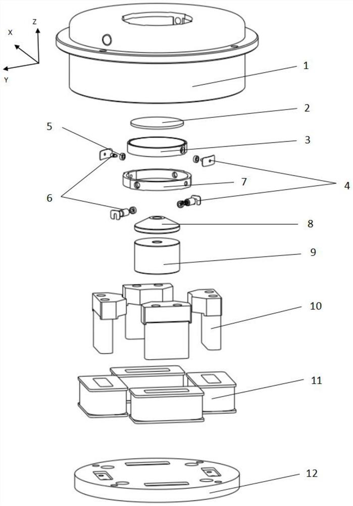
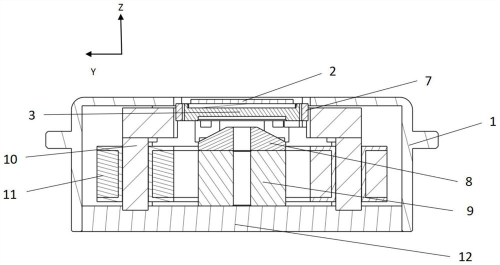
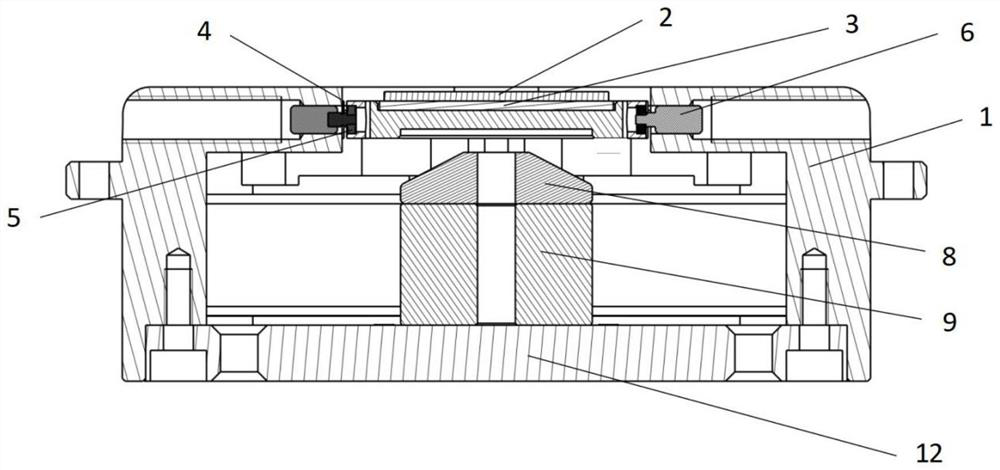
[0056] Please refer to Figure 1 to Figure 4 , The embodiment of the present invention provides an electromagnetic driving and supporting structure for a two-dimensional fast mirror, which includes a mirror 2 , a mirror bracket 3 , a rigid support assembly, a voice coil motor, a base 12 and a housing 1 .

[0057] The mirror 2 is supported by the mirror bracket 3 on the ri...


PUM


Abstract

The invention discloses an electromagnetic driving and supporting structure of a two-dimensional fast reflecting mirror. The electromagnetic driving and supporting structure comprises a reflecting mirror, a reflecting mirror support, a rigid supporting assembly, a voice coil motor, a base and a shell. The reflecting mirror is supported on the rigid bearing assembly by the reflecting mirror bracket; the reflector bracket rotates around a first shaft relative to the rigid bearing assembly; the rigid bearing assembly is supported on the shell; the rigid bearing assembly rotates around a second shaft relative to the shell; the shell is fixed on the base; and the voice coil motor is fixed between the shell and the base. According to the invention, two-dimensional co-pivot rotation can be realized, and a mirror surface deflection angle of more than + / -20 degrees is achieved; large impact vibration can be resisted; and the axial height of the fast reflecting mirror device can be saved, so that the structure of the device is more compact.

Description

technical field [0001] The invention relates to the technical field of photoelectric scanning and tracking, in particular to an electromagnetic driving and supporting structure of a two-dimensional fast mirror. Background technique [0002] The fast reflector is a component that works between the light source or receiver and the target to adjust and stabilize the visual axis of the optical system or the beam pointing. By using a voice coil motor to precisely control the deflection direction of the reflector, the beam deflection angle can be precisely controlled. It is used to realize the rapid adjustment of the "deflection-tilt" azimuth angle of the mirror, and can be used in applications such as line-of-sight stabilization or scan compensation in the optoelectronic field. Due to its advantages of compact structure, fast response, high working bandwidth and high pointing accuracy, it is widely used in astronomical telescopes, adaptive optics, image motion compensation, free ...

Claims


Application Information

Patent Timeline
Patent Type & Authority Applications(China)
IPC IPC(8): G02B7/182G02B7/198H02K41/03
Inventor 肖立亮孔凡辉
Owner 北京瑞控信科技股份有限公司
Why Eureka
Try Eureka