Spray plate, MOCVD (Metal Organic Chemical Vapor Deposition) reaction system with spray plate and use method of MOCVD reaction system

A reaction system and spray plate technology, applied in the field of MOCVD reaction system, can solve the problems of poor temperature uniformity of the spray plate, poor thermal conductivity of thin plates, poor thermal conductivity of stainless steel, etc., so as to reduce maintenance costs and time, and alleviate the effect of clogging problems.

Active Publication Date: 2022-04-15
EASTERN SUPERCONDUCTOR SCI & TECH SUZHOU CO LTD
View PDF16 Cites 4 Cited by
  • Summary
  • Abstract
  • Description
  • Claims
  • Application Information

AI Technical Summary

Problems solved by technology

But the heat conduction of stainless steel is poor, the heat conduction of thin plates is also poor, and the temperature uniformity of the spray plate is also poor.

Method used


Image

  • Spray plate, MOCVD (Metal Organic Chemical Vapor Deposition) reaction system with spray plate and use method of MOCVD reaction system
  • Spray plate, MOCVD (Metal Organic Chemical Vapor Deposition) reaction system with spray plate and use method of MOCVD reaction system
  • Spray plate, MOCVD (Metal Organic Chemical Vapor Deposition) reaction system with spray plate and use method of MOCVD reaction system

Examples


Embodiment 1

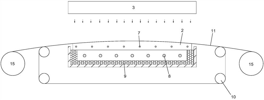
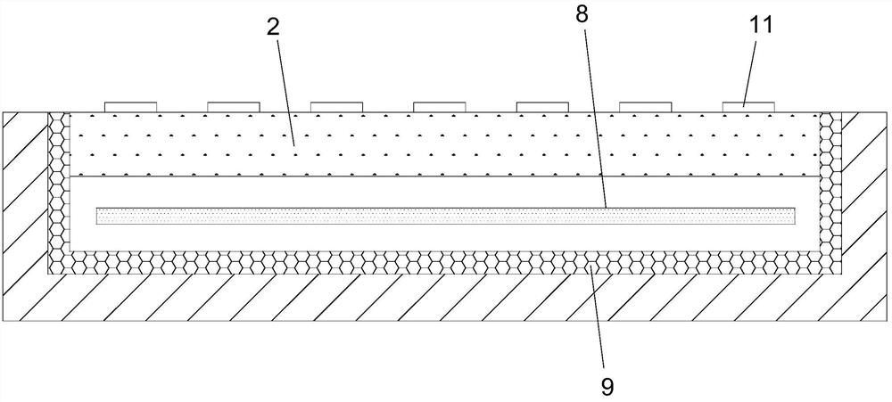
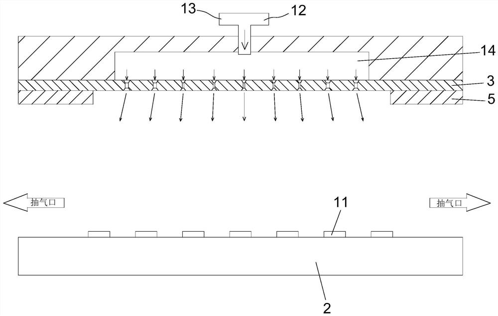
[0063] refer to Figure 6 As shown, the same as the traditional MOCVD reaction system, the MOCVD reaction system of this embodiment also includes: MOCVD reaction chamber 1, heating substrate 2 arranged in the MOCVD reaction chamber, and shower plate 3 above the heating substrate. For the convenience of describing the technical solution of the present application, the length dimension of the shower plate 3 is defined as along the direction of travel of the strip 11 during the deposition operation (i.e. Figure 6 In the dimension perpendicular to the inside and outside direction of the paper surface), the width dimension of the shower plate 3 is defined as along the width direction of the strip 11 during the deposition operation (ie Figure 6 The dimension parallel to the left-right direction of the paper). Obviously the width and length of the shower plate 3 are perpendicular. Moreover, the aforementioned definition of the length and width of the shower plate 3 conforms to co...

Embodiment 2

[0072] Such as Figure 8 and Figure 9 As shown, the structure of the MOCVD reaction system of this embodiment is basically the same as that of Embodiment 1, the difference is only that: the shower plate 3 of this embodiment is fixedly connected with the guide plate 4 located below each source reaction gas nozzle hole 303 .

[0073] During operation, the source reaction gas ejected from the source reaction gas nozzle 303 is blocked by the deflector 4 and flows to both sides, which increases the lateral flow of the source reaction gas, especially oxygen.

[0074] The width of the deflector 4 is 3.5mm, which is larger than the diameter of the lower orifice of any source reaction gas nozzle 303 . And this deflector plate 4 is fixed on the shower plate 3 with the screw locking of 2mm diameter.

Embodiment 3

[0076] In order to improve productivity and deposition efficiency, people hope that the number of winding system (that is, the number of heating strips on the substrate) should be as many as possible, but the number of passes makes some problems more and more serious, one of the main problems is It is the problem of the uniformity of oxygen distribution in the MOCVD reaction chamber. For the MOCVD reaction system with a very large number of channels, in order to further improve the temperature uniformity of the spray plate 3 and the uniformity of oxygen in the reaction chamber. In this embodiment, two source reaction gas sub-channels 304 located on the radial sides of the source reaction gas flow channel 302 are also formed in the spray plate 3, and the inner wall surface of each source reaction gas sub-channel 304 is formed with A plurality of source reaction gas sub-spray holes 305 extending downward to the lower surface of the shower plate 3, such as Figure 10 .

[0077] Du...


PUM


Abstract

The invention relates to a spraying plate, an MOCVD (Metal Organic Chemical Vapor Deposition) reaction system provided with the spraying plate and a use method of the MOCVD reaction system. The MOCVD reaction system comprises a heating substrate, the spraying plate, an MOCVD reaction cavity, a cooler and an extraction opening, a source reaction gas flow channel which is located in the middle of the width of the spraying plate and extends in the length direction of the spraying plate is formed in the spraying plate, and a plurality of source reaction gas spraying holes which extend downwards to the lower surface of the spraying plate are formed in the inner wall face of the source reaction gas flow channel. According to the application, the mixing uniformity of the metal organic source gas and the source reaction gas in the reaction cavity and the temperature uniformity of the spraying plate can be improved, so that the production quality of the superconducting tape is improved.

Description

technical field [0001] The present application relates to the field of making superconducting strips, in particular to a shower plate, an MOCVD reaction system equipped with the shower plate, and a method for using the same. Background technique [0002] The second-generation high-temperature superconducting tape has zero resistance characteristics, so the current-carrying capacity of the superconducting cable is 5 to 10 times that of the current copper cable, and the volume and weight of the superconducting motor can be reduced to 1 / 4 of the original. It will bring revolutionary changes and industrial upgrading in many fields, and has huge market potential. [0003] The preparation of high-temperature superconducting strips is to deposit high-temperature superconducting thin films on cheap, flexible metal substrates. The metal baseband is generally thousands to hundreds of meters long, tens of microns thick, and 10-20 mm wide. Using the roll-to-roll MOCVD method, the supe...

Claims


Application Information

Patent Timeline
Patent Type & Authority Applications(China)
IPC IPC(8): C23C16/455H01B12/06
CPCH01B12/06C23C16/455C23C16/54B05B7/00Y02E40/60
Inventor 熊旭明王延恺田卡袁文蔡渊迮建军
Owner EASTERN SUPERCONDUCTOR SCI & TECH SUZHOU CO LTD
Why Eureka
Try Eureka