Ultralow-temperature liquefied gas pressure vessel for improving heat insulation effect

A technology for liquefied gas and pressure vessels, which is applied to non-pressure vessels, container filling methods, container discharge methods, etc., can solve the problems of insufficient use of cooling capacity and affect the thermal insulation effect of ultra-low temperature liquefied gas pressure vessels, and improve the thermal insulation effect Effect

Active Publication Date: 2022-04-15
JIANGYIN FUREN HIGH TECH
View PDF8 Cites 0 Cited by
  • Summary
  • Abstract
  • Description
  • Claims
  • Application Information

AI Technical Summary

Problems solved by technology

[0004] One is that the support structure between the inner container and the outer container will produce a certain amount of heat transfer, which affects the insulation effect of the ultra-low temperature liquefied gas pressure vessel
[0005] Second, the cooling capacity of the liquefied gas released under overpressure is not fully utilized, which will also affect the insulation effect of the ultra-low temperature liquefied gas pressure vessel

Method used


Image

  • Ultralow-temperature liquefied gas pressure vessel for improving heat insulation effect
  • Ultralow-temperature liquefied gas pressure vessel for improving heat insulation effect
  • Ultralow-temperature liquefied gas pressure vessel for improving heat insulation effect

Examples


Embodiment 1

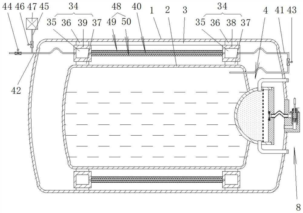
[0040] Such as Figure 1 to 7 The exemplary embodiment of the present invention is an ultra-low temperature liquefied gas pressure vessel for increasing the heat insulating effect, including the insulator 1, the outer container 2, formed in a sandwich space between the insulator 1 and the outer container 2. 3. Supporting the support assembly 34 between the instructor 1 and the outer container 2, the support assembly 34 includes a pair of support loops 38, 39 with an annular hollow internal cavity 35, disposed in the support ring. 38, 39 The number of several numbers arranged along the circumferential intervals is used to support the outer support of the outer wall of the outer container 2, which is disposed in the support ring 38, 39, and several quantities arranged along the circumferential interval for support. The inside support of the outer wall of the contentor 1; the pair of support ring 38, 39 includes a first support ring 38 and a second support ring 39, and the annular hol...

Embodiment 2

[0057] The replaceable molecular sieve adapter in the above Example 1 adopts the following structure:

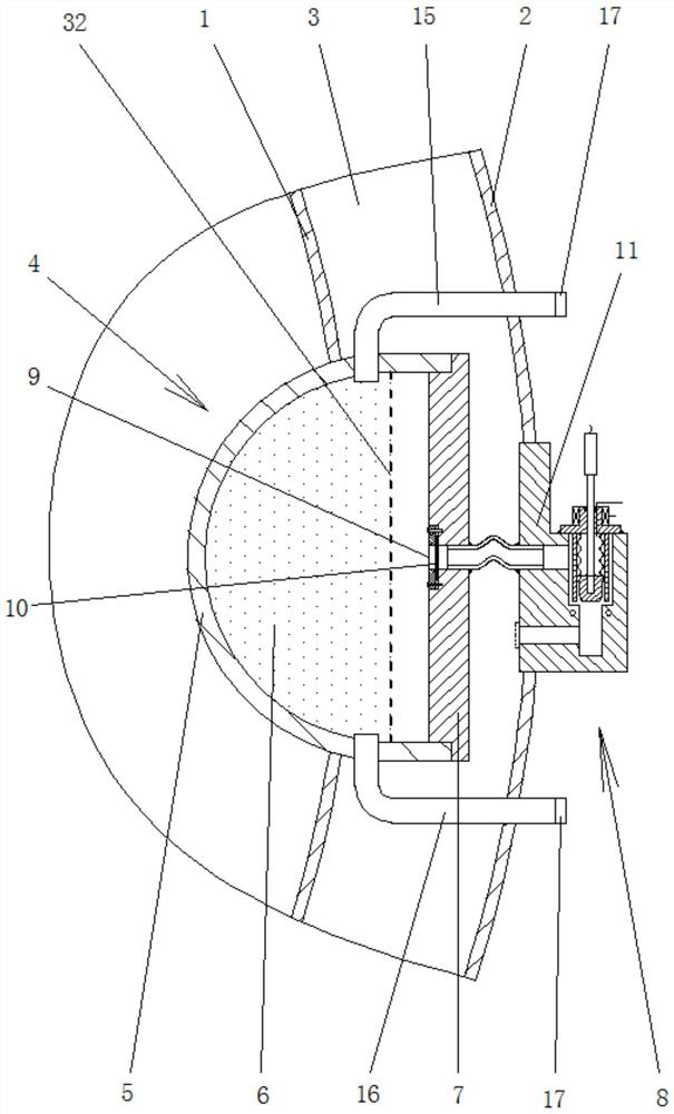
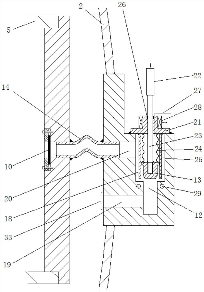
[0058] The molecular sieve adapter 4 includes a molecular sieve sucking case 5 disposed on the inscribed 1 tank, which is filled inside the molecular sieve adsorbed casing 5 for adsorbing a molecular sieve 6 of the inner gas and moisture of the clamping space 3, provided in The molecular sieve sucking cassette 5 is configured to enclose the molecular sieve 6 in the casing 7 in the inside of the molecular sieve suction case 5, a vacuum environment for a vacuum environment on the outer container 2 tank 8, the box A adsorbed hole 9 is provided on the cover 7, and the adsorbent hole 9 is provided with a blanked sealing sheet 10 which includes a valve body 11 and an adsorbent passage disposed on the valve body 11. The vacuum sealing hole 12 is disposed on the adsorption passage, which is provided on the vacuum sealing hole 12 for blocking or opening the thermal expansion sealing plun...


PUM


Abstract

The ultralow-temperature liquefied gas pressure container comprises an inner container body, an outer container body and a supporting assembly supported between the inner container body and the outer container body, and the supporting assembly comprises a first supporting ring with an annular hollow inner cavity and a second supporting ring with an annular hollow inner cavity. A gas throttle pipe is arranged between the annular hollow inner cavities of the first support ring and the second support ring; a first gas pipeline is led out of the upper gas space inside the inner container, the first gas pipeline enters the annular hollow inner cavity of the first supporting ring after being led out, and a second gas pipeline is led out of the annular hollow inner cavity of the second supporting ring; a first valve is arranged on the first gas pipeline, a second valve is arranged on the second gas pipeline, a branch gas pipeline is arranged at a section of position between the second valve and the outer container on the second gas pipeline, and a third valve and a vacuumizing device are sequentially arranged on the branch gas pipeline. The heat insulation effect of the ultralow-temperature liquefied gas pressure vessel is improved.

Description

Technical field [0001] The present invention relates to the field of low temperature pressure vessels, and more particularly to an ultra-low temperature liquefied gas pressure vessel for increasing the heat insulating effect. Background technique [0002] Ultra-low temperature liquefied gas storage pressure vessels are a deep-cooling pressure vessel for storing ultra-low temperature liquefied gas, which uses a double layer structure, including a sewer and outer container, an extension, and an outer container to form a vacuum interlayer space to isolate external heat. Pass to ensure the safety of low temperature liquefied gas in the contentor. In order to improve the heat insulating performance, it is generally wound around the insulation insulation material to reduce heat transfer, convection, and radiation to reach heat insulation, and store low temperature liquid. The arrangement of the insulation of the inside the can body in the interlayer vacuum and the insulation of the hea...

Claims


Application Information

Patent Timeline
Patent Type & Authority Applications(China)
IPC IPC(8): F17C3/04F17C3/08F17C3/10F17C13/00F17C13/04
Inventor 朱明国徐兴宝钱丽君陈凯罗展鹏计徐伟刘胜
Owner JIANGYIN FUREN HIGH TECH
Why Eureka
Try Eureka