Eureka AIR delivers breakthrough ideas for toughest innovation challenges, trusted by R&D personnel around the world.

Peak holding circuit with peak mark output

A technology of peak hold circuit and peak detection circuit, which is applied in the direction of electrical components, pulse processing, pulse technology, etc., can solve the problems of not being able to output peak signal, only outputting peak signal, limiting precision and stability, etc., to avoid precision Reduce, improve detection accuracy and energy resolution, and improve the effect of carrying capacity

Pending Publication Date: 2022-04-19
重庆中易智芯科技有限责任公司
View PDF0 Cites 0 Cited by
  • Summary
  • Abstract
  • Description
  • Claims
  • Application Information

AI Technical Summary

Problems solved by technology

However, non-idealities in amplifiers and feedback components greatly limit their accuracy and stability, as figure 1
In addition, because the classic peak detection and hold circuit only uses one PMOS tube to charge and has only one output terminal, it can only output the peak signal and cannot output the peak marker signal. Flag digital signal output for accurate peak arrival time stamping

Method used


Image

  • Peak holding circuit with peak mark output
  • Peak holding circuit with peak mark output
  • Peak holding circuit with peak mark output

Examples


Embodiment

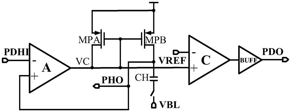
[0028] Such as figure 2 , Figure 9 Shown, including peak hold circuit, peak detection circuit, peak marker output buffer. Among them, the output of the peak hold circuit comes from the output of the previous stage, which can be the output of the filter shaper or the radiation signal output by other detection circuits. The two output terminals of the peak hold circuit are the peak output and the current mirror voltage signal respectively. The current mirror voltage signal is connected to the input terminal of the peak detection circuit, and the output terminal of the peak detection circuit is connected to the peak marker output buffer to output the peak marker signal to other modules.

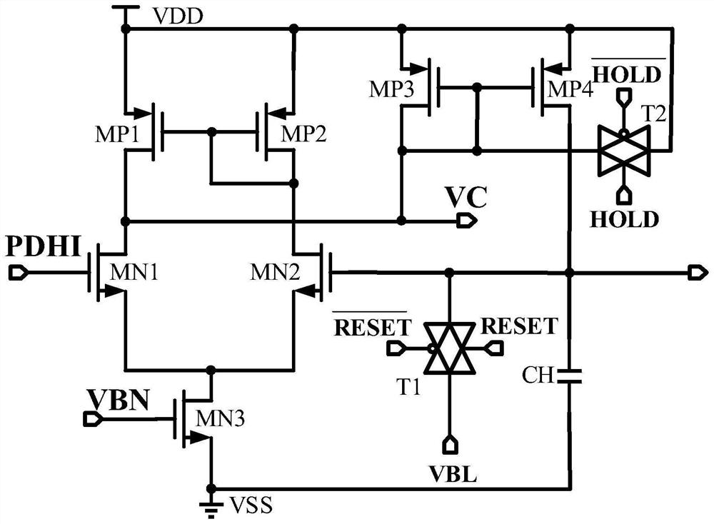
[0029] Such as image 3 As shown, the peak hold circuit includes 4 PMOS transistors, respectively MP1, MP2, MP3, MP4, three NMOS transistors, respectively MN1, MN2, MN3, a holding capacitor CH, two transmission gates T1, T2, where T1 and T2 are controlled by external RESET signal and HOLD s...


PUM


Abstract

The invention claims to protect a peak holding circuit with peak mark output. The peak holding circuit comprises a peak holding circuit, a peak detection circuit and a peak mark output buffer. Wherein the output of the peak holding circuit comes from the output of the previous stage and can be the output of a filter former or a radiation signal output by other detection circuits, the two output ends of the peak holding circuit are a peak output and a current mirror voltage signal respectively, and the current mirror voltage signal is connected to the input end of the peak detection circuit. The output end of the peak value detection circuit is connected to a peak value mark output buffer, and the peak value mark output buffer outputs a peak value mark signal to other modules. The peak holding circuit can hold the waveform of a previous-stage voltage signal at a peak value, the peak detection circuit can quickly respond and output a corresponding marking signal when the peak value arrives, and the peak marking output buffer can convert the marking signal output by the peak detection circuit into a corresponding pulse signal.

Description

technical field [0001] The invention belongs to the technical field of analog integrated circuit design, and in particular relates to a peak hold circuit with a peak mark output, in particular to a radiation detector readout circuit. Background technique [0002] Once discovered, radiation phenomena are applied to various fields of life, such as space exploration, high-energy physics, security inspection, nuclear medical imaging, etc. How to quickly and accurately measure radiation energy has become the most critical issue in these fields. The peak hold circuit is a key element in nuclear electronic signal processing, and has been fully integrated into multiple front-end dedicated readout chips as an important module. In CMOS designs, classic peak-and-hold circuits use a MOS current source as a rectifying element within the feedback loop of a high-gain amplifier. However, non-idealities in amplifiers and feedback components greatly limit their accuracy and stability, as fi...

Claims


Application Information

Patent Timeline
Patent Type & Authority Applications(China)
IPC IPC(8): H03K5/1532
CPCH03K5/1532
Inventor 王巍黎淼赵汝法樊琦
Owner 重庆中易智芯科技有限责任公司
Why Eureka
Eureka Blog
Learn More