
Electric pulse auxiliary machining device for machining slender shaft parts and machining method of electric pulse auxiliary machining device

A part processing and auxiliary processing technology, applied in the field of mechanical processing, can solve the problems of insufficient surface roughness and geometric accuracy, and achieve excellent chatter and deformation, prolong service life, and suppress chatter and deformation.

Pending Publication Date: 2022-04-22
HUNAN UNIV OF SCI & TECH
View PDF13 Cites 0 Cited by
  • Summary
  • Abstract
  • Description
  • Claims
  • Application Information

AI Technical Summary

Problems solved by technology

However, it is not enough to obtain satisfactory surface roughness and geometric accuracy after processing with a single process method

Method used


Image

  • Electric pulse auxiliary machining device for machining slender shaft parts and machining method of electric pulse auxiliary machining device
  • Electric pulse auxiliary machining device for machining slender shaft parts and machining method of electric pulse auxiliary machining device
  • Electric pulse auxiliary machining device for machining slender shaft parts and machining method of electric pulse auxiliary machining device

Examples


Embodiment 1

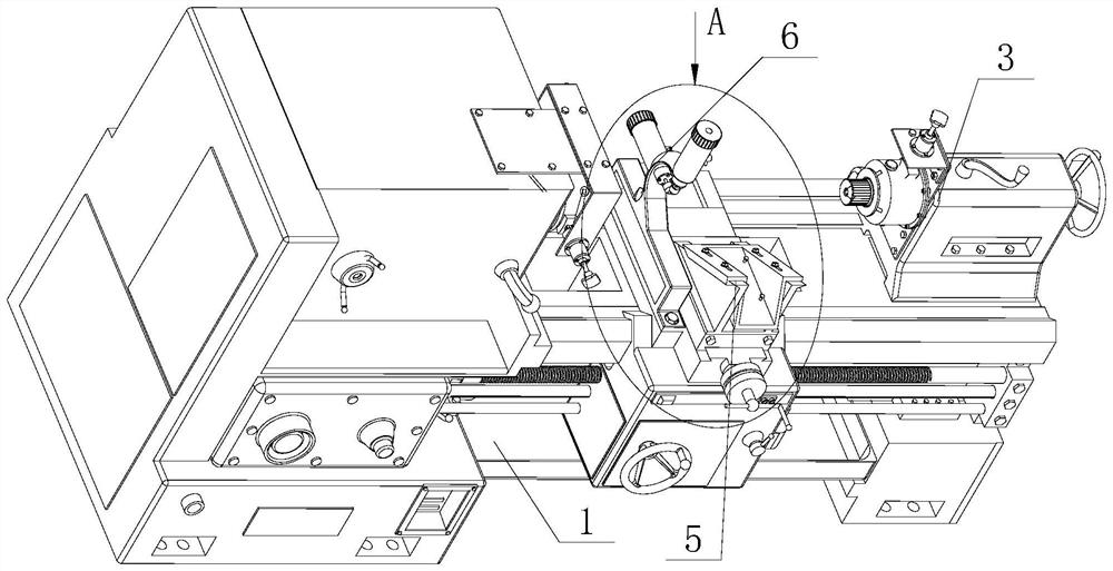
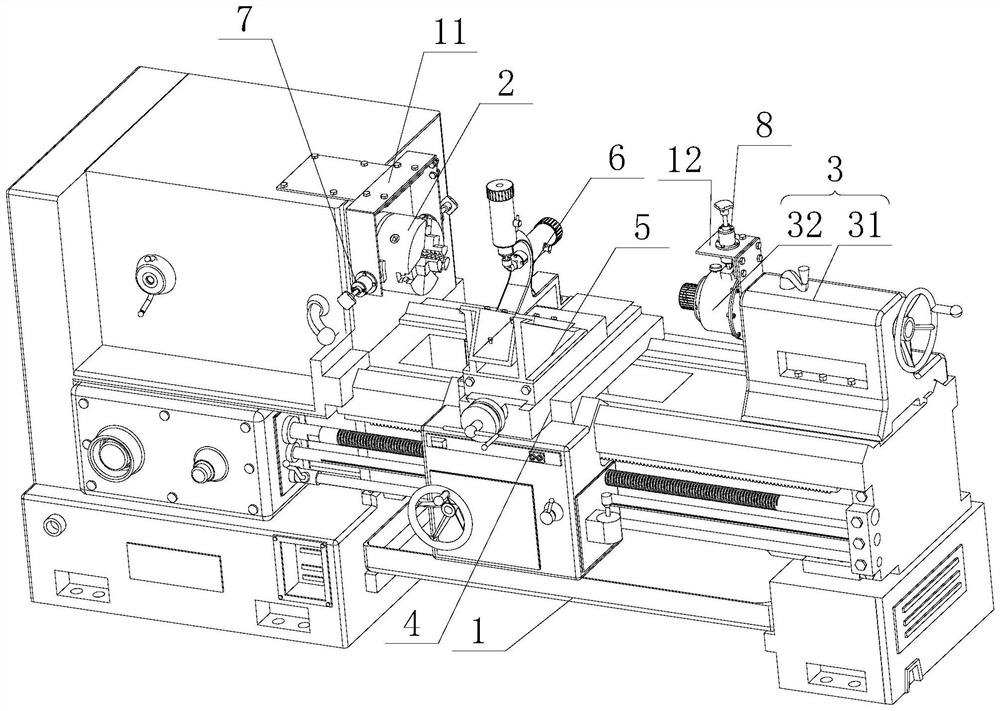
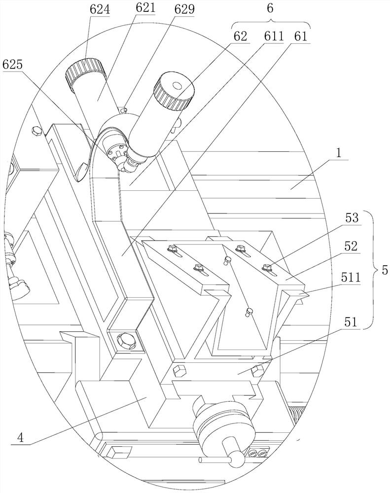
[0038] Figure 1 to Figure 8 An embodiment of the electric pulse auxiliary processing device for processing slender shaft parts of the present invention is shown. The electric pulse auxiliary processing device for processing slender shaft parts includes a machine tool 1, and the front and rear ends of the machine tool 1 are respectively provided with clamps. The disc mechanism 2 and the tensioned tailstock 3, the machine tool 1 is provided with a slide box 4 between the chuck mechanism 2 and the tensioned tailstock 3, and the slide box 4 is provided with a tool mounting frame 5 and a tool holder 6 , the chuck mechanism 2 is provided with a chuck power connection mechanism 7, and the tension type tailstock 3 is provided with a tailstock power connection mechanism 8, and the chuck power connection mechanism 7 and the tailstock power connection mechanism 8 are connected with the positive pole and the negative pole of the pulse power supply. Respectively connected, the tool rest 6...

Embodiment 2

[0056] An electric pulse assisted processing method for processing slender shaft parts, which is carried out by using the electric pulse assisted processing device for processing slender shaft parts in Embodiment 1, comprising the following steps:

[0057] Step S1, installation of slender shaft parts: fasten one end of the slender shaft parts to the chuck mechanism 2 on the machine tool 1, and tighten the other end to the tensioned tailstock 3. Specifically, one end of the slender shaft part is clamped on the chuck mechanism 2 on the machine tool 1, and the other end is clamped on the clamping mechanism 34 of the tensioned tailstock 3. Next, the axial tension force is formed on the slender shaft parts.

[0058] Step S2, radial support of slender shaft parts: adjust the position of the tool rest 6, make the slender shaft parts pass through the space 611, and then make each magnetorheological damping support assembly 62 radially support the slender shaft parts , the magneto-rhe...


PUM


Abstract

The electric pulse auxiliary machining device comprises a machine tool, the machine tool is provided with a chuck mechanism, a tensioning type tailstock and a sliding box, the sliding box is provided with a tool mounting frame and a follow rest, the chuck mechanism is provided with a chuck power connection mechanism, the tensioning type tailstock is provided with a tailstock power connection mechanism, and the follow rest is provided with a follow rest. The chuck power connection mechanism and the tailstock power connection mechanism are connected with the positive electrode and the negative electrode of the pulse power source respectively, the follow rest comprises a mounting base and at least two magneto-rheological damping supporting assemblies, the mounting base is fixed to the sliding box and provided with a penetrating space, and the magneto-rheological damping supporting assemblies are arranged on the mounting base. The invention further discloses an electric pulse auxiliary machining method for machining the slender shaft type part. The method comprises the steps of slender shaft type part installation, radial supporting and cutting machining. According to the electric pulse auxiliary machining device for machining the slender shaft parts and the machining method of the electric pulse auxiliary machining device, the slender shaft parts are axially and oppositely pulled, radially supported and electrified, so that the machining precision and the machining efficiency are improved.

Description

technical field [0001] The invention relates to the technical field of mechanical processing, in particular to an electric pulse auxiliary processing device for processing slender shaft parts and a processing method thereof. Background technique [0002] With the development of civil and national defense industries, higher requirements are put forward for the manufacturing level of parts. Among them, the efficient and high-precision machining of slender shaft parts is an urgent problem to be solved in the current civil and national defense industries. Slender shaft parts are one of the most difficult parts in mechanical processing. Such parts have a large aspect ratio and have straightness requirements for the axis and contour lines. They are prone to bending and vibration during machining, and are difficult to process after machining. Obtain satisfactory surface roughness and geometric accuracy. [0003] The current ordinary horizontal lathe has low machining accuracy and ...

Claims


Application Information

Patent Timeline
Patent Type & Authority Applications(China)
IPC IPC(8): B23H5/04B23H11/00
CPCB23H5/04B23H11/003B23H2300/10
Inventor 孙富建罗长庚肖罡屈盛官
Owner HUNAN UNIV OF SCI & TECH
Learn More