Eureka AIR delivers breakthrough ideas for toughest innovation challenges, trusted by R&D personnel around the world.

Multi-band linear frequency modulation signal generation method capable of flexibly selecting frequency

A linear frequency modulation signal and multi-band technology, applied in the field of optical communication and microwave, can solve the problems of large volume, single function, large loss, etc., achieve the effect of large operating frequency range, avoid phase noise, and ensure stability

Pending Publication Date: 2022-04-22
XIDIAN UNIV
View PDF7 Cites 2 Cited by
  • Summary
  • Abstract
  • Description
  • Claims
  • Application Information

AI Technical Summary

Problems solved by technology

In the first solution, although the system is flexible and scalable, the coupling between free space and optical fiber will increase the loss and complexity of the system, and the system usually faces the problems of large volume and large loss
In the second scheme, there is no need for spatial light processing, and the system will be more stable; using the flexible modulation mode and variable system structure of the electro-optic modulator, the chirp signal can be obtained simply and effectively, and the time-width bandwidth of the generated signal can be greatly improved. However, most of the solutions have a single function and can only generate chirp signals at a single frequency, which is difficult to apply to multi-band radar systems

Method used


Image

  • Multi-band linear frequency modulation signal generation method capable of flexibly selecting frequency
  • Multi-band linear frequency modulation signal generation method capable of flexibly selecting frequency
  • Multi-band linear frequency modulation signal generation method capable of flexibly selecting frequency

Examples


Embodiment Construction

[0026] Below in conjunction with accompanying drawing the embodiment of the present invention is described in detail: present embodiment is carried out under the premise of technical solution of the present invention, has provided detailed implementation mode and concrete operation process, but protection scope of the present invention is not limited to subordinates the embodiment.

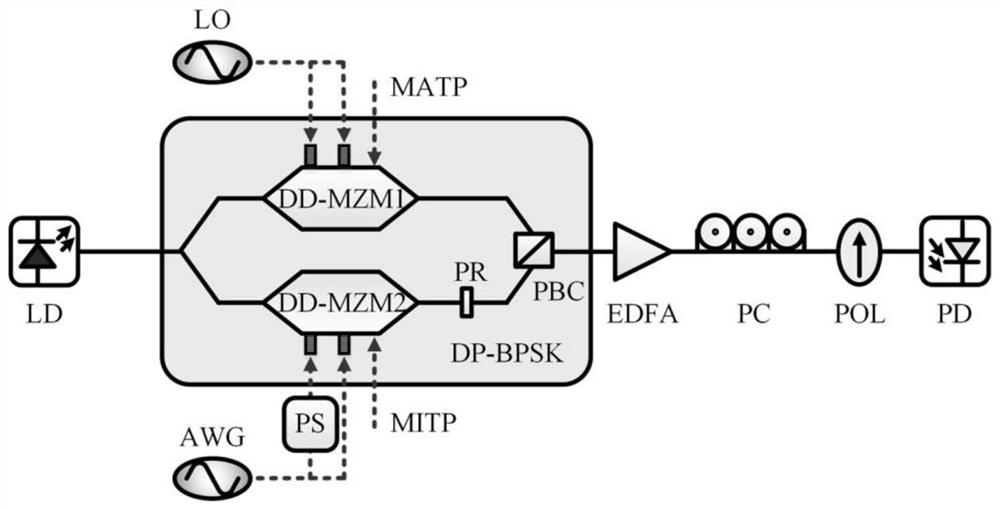
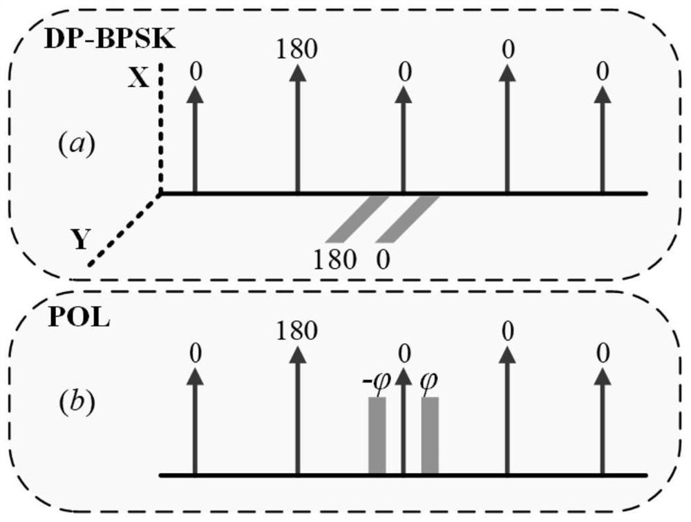
[0027] figure 1 Schematic diagram of the generation method for multi-band chirp signals with flexible frequency selection. The device includes 1 laser source LD, 2 dual-polarization binary phase-shift keying modulator DP-BPSK, 3 dual-drive Mach-Zehnder modulator DD-MZM, 4 90° polarization rotator PR, 5 phase shifter PS, 6 polarized beams Synthesizer PBC, 7 arbitrary waveform generator AWG, 8 erbium-doped fiber amplifier EDFA, 9 polarization controller PC, 10 polarizer POL, 11 photodetector PD. DP-BPSK realizes the polarization multiplexing of two optical signals, and the upper arm DD-MZM1 works ...


PUM


Abstract

The invention discloses a multi-band linear frequency modulation signal generation method capable of flexibly selecting frequencies, and relates to the technical field of microwaves and the technical field of optical communication. The method is shown in a figure 1 in the specification, and comprises a laser device LD, a dual-polarization binary phase shift keying modulator DP-BPSK, an arbitrary waveform generator AWG, an erbium-doped fiber amplifier EDFA, a polarization controller PC, a polarizer POL and a photoelectric detector PD. Phase modulation is carried out on a local oscillator signal through the DD-MZM1 of the DP-BPSK upper arm, and carrier suppression double-sideband modulation is carried out on an IF-LFM signal through the DD-MZM2 of the DP-BPSK lower arm; the PC is adjusted, the phase difference between the two polarization states is controlled, and then a multiband linear frequency modulation signal can be obtained after POL and photoelectric detection. According to the invention, the electronic bottleneck of the electric field technology is overcome, and the characteristic of flexible frequency tuning is added; multi-band signals are generated at the same time, so that the system has potential application value in a multi-band radar and a distributed radar system.

Description

technical field [0001] The invention relates to the technical field of optical communication and microwave technology, and mainly relates to the generation of chirp signals by using photonics technology. Background technique [0002] The increasingly complex detection environment puts forward higher requirements for radar detection. When the radar system detects targets, the detection distance and distance resolution are indicators that need to be considered at the same time. In order to increase the detection distance, it is necessary to increase the average transmission power and the pulse of the detection signal. The width needs to be relatively large. In order to improve the distance resolution, the detection signal needs to have a large bandwidth, which is contradictory to the general signal, so the pulse compression signal came into being. Chirp signal is one of the microwave waveforms widely used for pulse compression in modern radar systems. It has received more and ...

Claims


Application Information

Patent Timeline
Patent Type & Authority Applications(China)
IPC IPC(8): H04B10/516H04B10/556
CPCH04B10/5167H04B10/5561H04B10/5165
Inventor 薛寒文爱军门渊
Owner XIDIAN UNIV
Why Eureka
Eureka Blog
Learn More