Unmanned aerial vehicle swarm dense continuous emission control system based on high-speed optical fiber bus

A fiber optic bus and launch control technology, applied in signal transmission systems, non-electrical signal transmission systems, launch/drag transmissions, etc., can solve problems such as information error codes, complex links, electromagnetic interference, etc., and achieve simple and flexible hardware structure Effect of Topology, Reliable Transport Mechanism

Active Publication Date: 2022-04-26
BEIHANG UNIV
View PDF20 Cites 0 Cited by
  • Summary
  • Abstract
  • Description
  • Claims
  • Application Information

AI Technical Summary

Problems solved by technology

Specifically, in view of the UAV swarm system needs to have the mission deployment requirements of storage, transportation, and launch, and considering the efficiency and safety of the rocket boost control method, a UAV based on high-speed optical fiber bus is proposed. The swarm intensive continuous launch control system solves the impact of multiple sources of data, electromagnetic interference, information error codes, and complex links on rocket launch control, so as to ensure that the drone swarm system can reliably and stably carry out continuous intensive drones. emission

Method used


Image

  • Unmanned aerial vehicle swarm dense continuous emission control system based on high-speed optical fiber bus
  • Unmanned aerial vehicle swarm dense continuous emission control system based on high-speed optical fiber bus
  • Unmanned aerial vehicle swarm dense continuous emission control system based on high-speed optical fiber bus

Examples


Embodiment Construction

[0052] The present invention will be further limited below in conjunction with the accompanying drawings and embodiments, but not limited thereto.

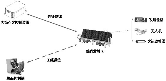
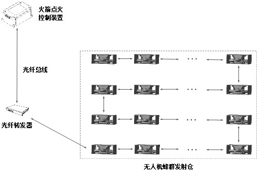
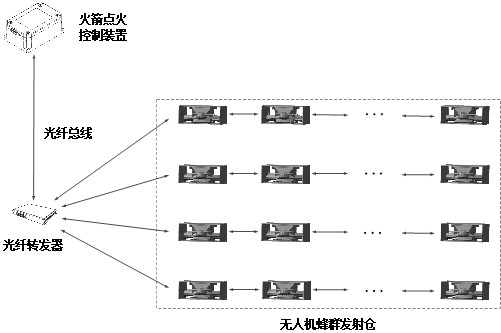
[0053] A high-speed fiber-optic bus-based dense continuous launch control system for UAV swarms consists of multiple components: swarm launch chambers, multiple UAVs, optical fiber transponders, rocket ignition control devices, several rocket boosters, Ground control stations such as figure 1 shown. The swarm launch cabin has N launch compartments, each of which is loaded with a UAV, and the serial number of the drone is 1~N; the fiber optic transponder is installed in the swarm launch cabin, and is interconnected with all aircrafts using the 1394b optical fiber bus ;The rocket ignition control device is located at a safe distance far from the swarm launch chamber, and it is connected to the optical fiber transponder through a 1394b optical fiber bus to realize interconnection with the aircraft; N rocket boosters are respectively...


PUM


Abstract

The invention discloses an unmanned aerial vehicle swarm intensive continuous launching control system based on a high-speed optical fiber bus. The unmanned aerial vehicle swarm intensive continuous launching control system comprises a swarm launching bin, N unmanned aerial vehicles, an optical fiber transponder, a rocket ignition control device, N rocket boosters and a ground control station. The bee colony launching bin is provided with N launching bin cells, and each bin cell is loaded with an unmanned aerial vehicle; the optical fiber transponder is installed in the bee colony launching bin and is interconnected with all the unmanned aerial vehicles through a high-speed optical fiber bus. The rocket ignition control device is connected to the optical fiber transponder through a high-speed optical fiber bus to realize interconnection networking with the unmanned aerial vehicle; the N rocket boosters are installed at the tail of the unmanned aerial vehicle and connected to the rocket ignition control device through ignition wires. And the ground control station performs information transmission with the unmanned aerial vehicle through wireless communication. The system can solve the influence of the problems of data multi-source, electromagnetic interference, information error codes, complex links and the like on rocket launching control, and ensures that the unmanned aerial vehicle swarm combat system reliably and stably carries out unmanned aerial vehicle continuous dense launching.

Description

technical field [0001] The invention relates to the field of UAV swarm emission control, in particular to a UAV swarm dense continuous emission control system based on a high-speed optical fiber bus. Background technique [0002] In recent years, with the continuous development and maturity of UAV technology and artificial intelligence technology, the UAV swarm mission system composed of a certain number of UAVs and centered on inter-machine coordination has received extensive attention and has become an important factor affecting the future. A new system of drone application trends. In future missions, using densely launched drone swarms in a saturated attack method can carry out tasks such as reconnaissance, interference, deception, and strikes on the target of the opponent, making it difficult for the opponent to defend against large-scale attacks. [0003] Fixed-wing UAV swarms for long-range missions cannot use the traditional runway for rapid and continuous take-off o...

Claims


Application Information

Patent Timeline
Patent Type & Authority Applications(China)
IPC IPC(8): G08C17/02G08C23/06B64F1/04
CPCG08C17/02G08C23/06B64F1/04
Inventor 王明李大伟杨炯
Owner BEIHANG UNIV
Why Eureka
Try Eureka