Textile printing and dyeing printing drying system and method

A drying system, textile printing and dyeing technology, applied in the direction of textiles and papermaking, printing, printing devices, etc., can solve the problems of the large horizontal space of the drying box, the difficulty of drying cloth printing, and the easy wrinkling of cloth, etc., to avoid Waste of hot air source, increase the drying path, and avoid the effect of blurred printing patterns

Active Publication Date: 2022-04-29
朱群益
View PDF23 Cites 1 Cited by
  • Summary
  • Abstract
  • Description
  • Claims
  • Application Information

AI Technical Summary

Problems solved by technology

[0003] At present, when drying printed fabrics, a single drying box is used to dry printed fabrics. A blowing nozzle for drying the fabrics is installed in the drying box, and the hot air source blows and dries the fabrics through the hot air nozzles. Dry, such textile fabric printing method has the following problems: 1. The drying path that the printed fabric passes through needs a certain length, thus causing the horizontal space of the drying box to be relatively large, and at the same time, the printed fabric is dried with time during the drying process. The moisture on the printed pattern is lost, causing the printed pattern to shrink, which makes the fabric easy to wrinkle
[0004] 2. The cloth is easy to generate water vapor during the drying process, and the water vapor flows in the drying box, resulting in more water content in the air, and the printing on the cloth is difficult to dry

Method used


Image

  • Textile printing and dyeing printing drying system and method
  • Textile printing and dyeing printing drying system and method
  • Textile printing and dyeing printing drying system and method

Examples


Embodiment Construction

[0033] Embodiments of the present invention will be described below with reference to the drawings. In the process, in order to ensure the clarity and convenience of illustration, we may exaggerate the width of the lines or the size of the constituent elements in the diagram.

[0034]In addition, the following terms are defined based on the functions in the present invention, and may be different according to the user's or operator's intention or practice. Therefore, these terms are defined based on the entire content of this specification.

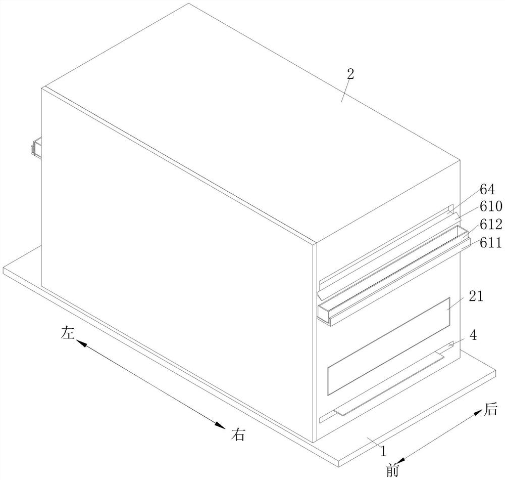
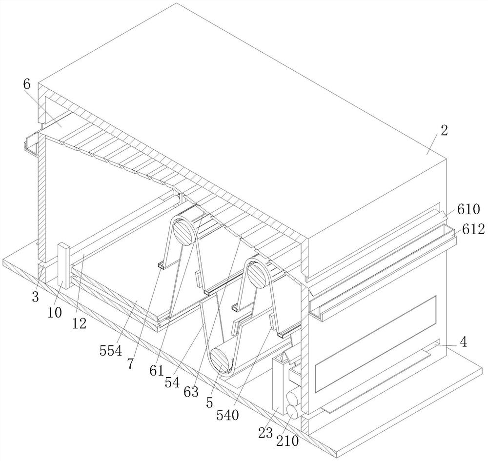
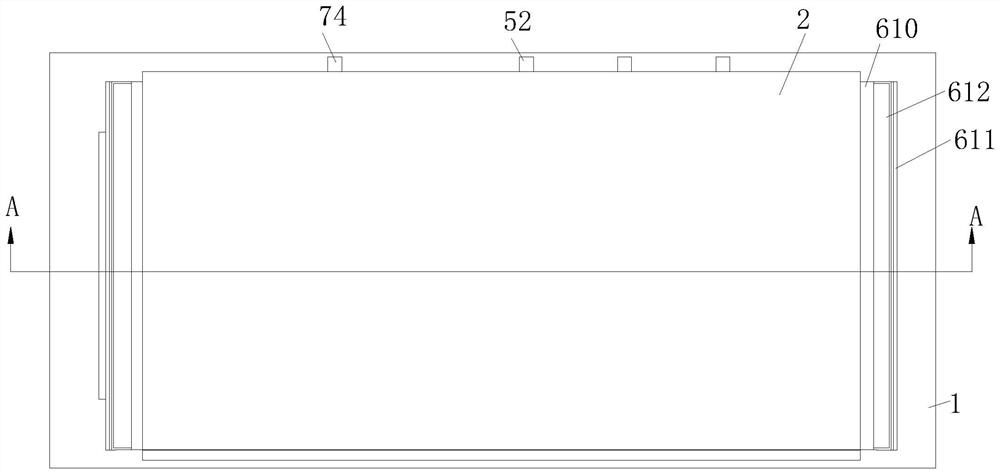
[0035] refer to figure 1 and figure 2 , a drying system for textile printing and dyeing, comprising a base frame 1, a drying box 2, a feed port 3 and a discharge port 4, the upper end surface of the base frame 1 is equipped with a drying box 2, and the drying box 2 The left and right ends of the lower side are respectively provided with a material inlet 3 and a material outlet 4. The inner wall of the drying box 2 is equipped with thr...


PUM


Abstract

The invention relates to the technical field of textile drying, in particular to a textile printing and dyeing printing drying system and method. The three drying mechanisms arranged in the inverted triangle shape are adopted, so that the transverse space proportion is reduced, meanwhile, the cloth drying path is increased, the cloth is rolled and flattened through cooperation of the abutting rollers and the anti-abrasion rollers while the cloth is dried by the drying mechanisms, and the cloth drying efficiency is improved. And an electric heating plate is installed at the right end of the V-shaped base, the electric heating plate irons the cloth to prevent the cloth from wrinkling, meanwhile, a steam condensation mechanism is adopted for cooling and discharging steam generated in the cloth drying process, and therefore the cloth drying effect is improved. And the phenomenon that the cloth drying speed is low due to the fact that the water content of air in the drying box is high is prevented, and therefore the cloth drying efficiency is improved.

Description

technical field [0001] The invention relates to the technical field of textile drying, in particular to a drying system and method for textile printing and dyeing. Background technique [0002] The original meaning of textile is taken from the general term of spinning and weaving, but with the development of science and technology, the current textile is not only traditional hand spinning and weaving, but also non-woven technology, among which weaving printing often appears in the textile industry In the production process of textile printing, it needs to go through multiple processes, one of which is the drying of textile printing. [0003] At present, when drying printed fabrics, a single drying box is used to dry printed fabrics. A blowing nozzle for drying the fabrics is installed in the drying box, and the hot air source blows and dries the fabrics through the hot air nozzles. Dry, such textile fabric printing method has the following problems: 1. The drying path that ...

Claims


Application Information

Patent Timeline
Patent Type & Authority Applications(China)
IPC IPC(8): B41J3/407B41J11/00D06C7/02D06C15/10
CPCB41J3/4078B41J11/0015B41J11/0024B41J11/0022D06C15/10D06C7/02Y02P70/10
Inventor 朱群益
Owner 朱群益
Why Eureka
Try Eureka