
Self-anchored polygonal photovoltaic support system

A technology of polygonal support and photovoltaic support, applied in the support structure of photovoltaic modules, photovoltaic power generation, photovoltaic modules, etc., can solve problems such as insufficient technical reliability, and achieve the effects of easy plane expansion, light weight and simple structure

Active Publication Date: 2022-04-29
POWERCHINA XIBEI ENG
View PDF8 Cites 1 Cited by
  • Summary
  • Abstract
  • Description
  • Claims
  • Application Information

AI Technical Summary

Problems solved by technology

[0006] In order to overcome the lack of technical reliability of existing flexible photovoltaic supports in typhoon areas, large-thickness silt areas and tidal areas, the present invention provides a self-anchored polygonal photovoltaic support system, which has strong adaptability to weak ground, large space span, The advantages of high rigidity, only vertical load transmission downward and strong resistance to progressive collapse

Method used


Image

  • Self-anchored polygonal photovoltaic support system
  • Self-anchored polygonal photovoltaic support system
  • Self-anchored polygonal photovoltaic support system

Examples


Embodiment 1

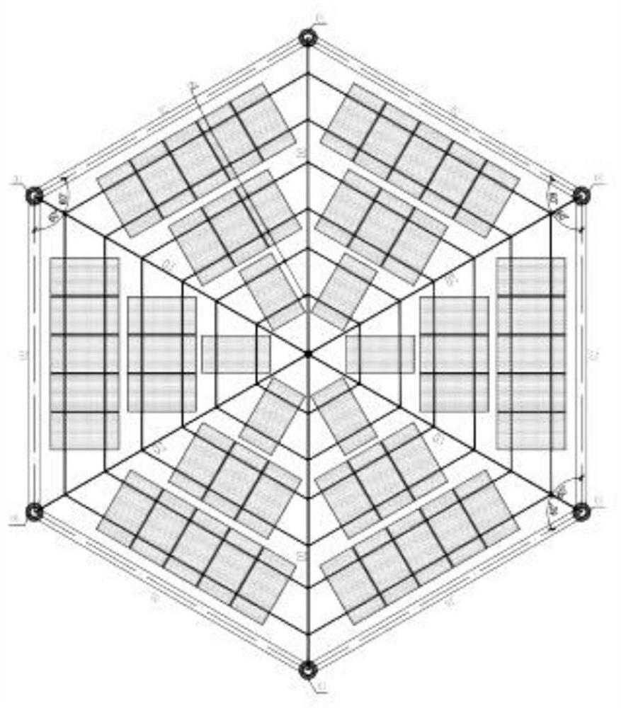
[0034] In order to overcome the lack of technical reliability of the existing flexible photovoltaic support in the typhoon area, large thickness silt area and tidal area, the present invention provides such Figure 1-7 A self-anchoring polygonal photovoltaic support system is shown, which has the advantages of strong adaptability to weak ground, large space span, high rigidity, downward transmission of only vertical loads, and strong resistance to continuous collapse.

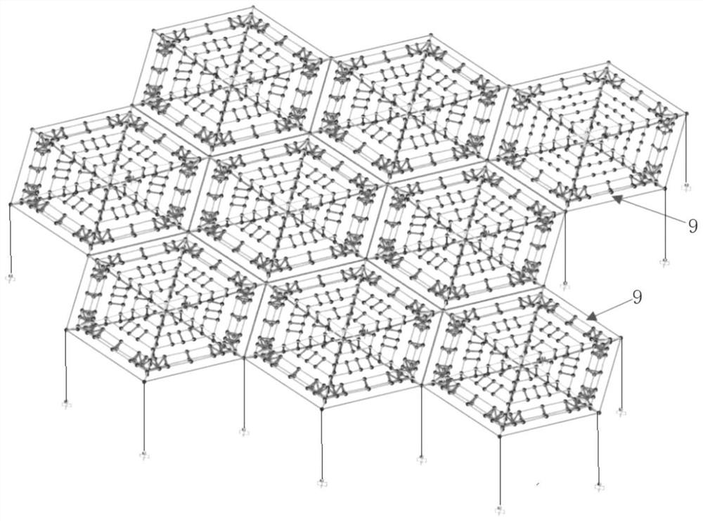
[0035] A self-anchored polygonal photovoltaic support system, including a support system and a plurality of self-anchored polygonal support units 9, the plurality of self-anchored polygonal support units 9 are spliced ​​with each other to form a rectangular array structure, and the polygonal support Unit 9 is located at the upper end of the support system.

[0036] In the present invention, a plurality of self-anchored polygonal units 9 are spliced ​​together to form a self-anchored polygonal support system wit...

Embodiment 2

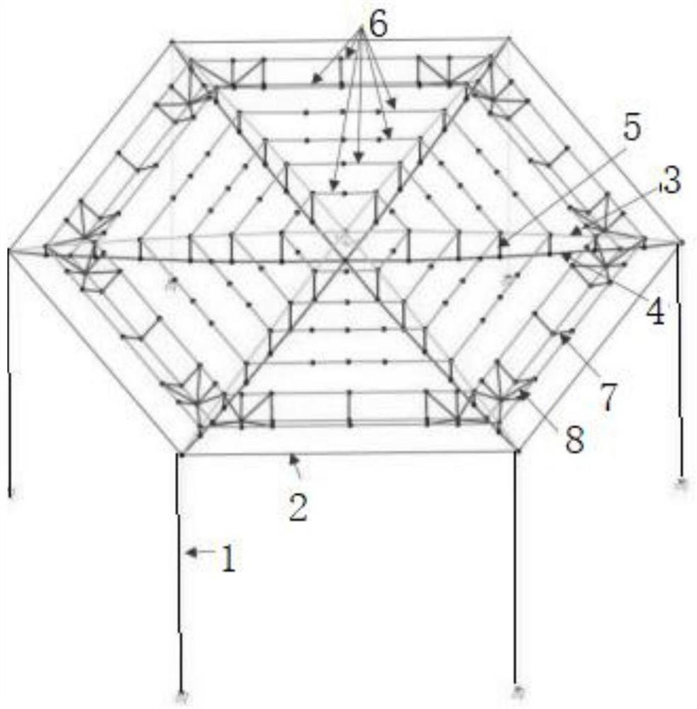
[0039]Based on the basis of Embodiment 1, in this embodiment, preferably, the self-anchoring polygonal support unit 9 is a hexagonal support unit, including a column 1, an edge tie rod 2, a radial upper cable 3, a radial The lower cable 4, the rigid tie rod 5 between the radial cables and the circumferential secondary cable 6, the edge tie rods 2 are six rods with the same length, and the six edge tie rods 2 form a regular hexagon; the radial upper cable 3 and the radial lower cable 4 are three, the radial lower cable 4 is arranged below the corresponding radial upper cable 3, and the radial upper cable 3 and the corresponding radial lower cable 4 are connected by a radial inter-cable rigid system. The rods 5 are connected into plane cable trusses; the three plane cable trusses are arranged on the three diagonals of the regular hexagon formed by the edge tie rods 2; The above-mentioned column 1 is arranged at the lower end of the joint of two adjacent edge tie rods 2 .

[004...


PUM


Abstract

The invention provides a self-anchored polygonal photovoltaic support system, which comprises a support system and a plurality of self-anchored polygonal support units, the plurality of self-anchored polygonal support units are mutually spliced to form a quasi-rectangular array structure, and the polygonal support units are arranged at the upper end of the support system. The self-anchored polygonal units are spliced, so that the span is large. The supporting system is an adjustable supporting rod. The lower end of the adjustable supporting rod is fixed at a required position, and the supporting rod is high enough and adjustable in height, so that the lower space of the self-anchored polygonal unit is large, and the requirements of agriculture-light complementation, forest-light complementation, grazing-light complementation, fishing-light complementation and other photovoltaic composite project application scenes on the larger and larger available space under the photovoltaic module are met.

Description

technical field [0001] The invention belongs to the field of photovoltaic power generation, in particular to a self-anchoring polygonal photovoltaic support system. Background technique [0002] The traditional strip-shaped photovoltaic support is in the form of a bent frame. In the short direction of the strip-shaped photovoltaic support structure, that is, the transverse direction of the structure, there are several bent frames made of cold-formed steel. On the top of the frame, along the length of the strip-shaped photovoltaic support structure, that is, the longitudinal direction of the structure, continuous purlins are set to support the photovoltaic modules. This form is simple in structure, easy to design, process and install, and was initially applied to flat Gobi terrain. [0003] With the development of the photovoltaic industry, it is also gradually applied to hilly and mountainous areas, as well as photovoltaic composite projects such as agricultural photovolta...

Claims


Application Information

Patent Timeline
Patent Type & Authority Applications(China)
IPC IPC(8): H02S20/30H02S20/10F24S25/16
CPCH02S20/30H02S20/10F24S25/16Y02E10/47Y02E10/50
Inventor 周康肖斌田伟辉徐翔吕宏伟崔振磊
Owner POWERCHINA XIBEI ENG
Learn More