Schottky diode capable of switching positive electrode and negative electrode
A technology of Schottky diodes, positive and negative poles, applied in the field of diodes, can solve the problems of difficult operation and long time consumption, and achieve the effects of low difficulty in operation, improved heat dissipation performance, and simple structure
- Summary
- Abstract
- Description
- Claims
- Application Information
AI Technical Summary
Problems solved by technology
Method used
Image


Examples
Embodiment 1
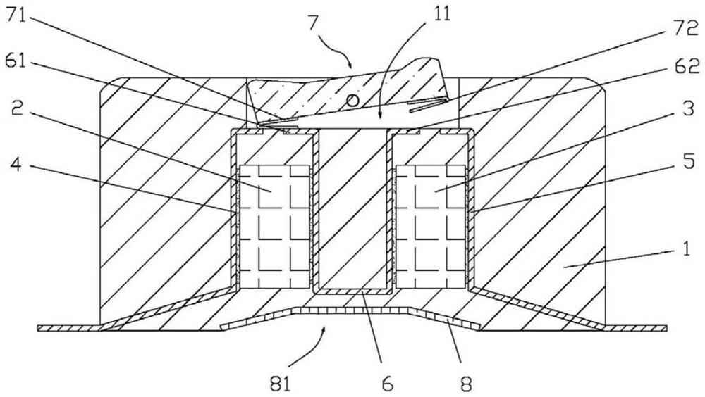
[0026] Such as figure 1 The shown Schottky diode with switchable positive and negative poles includes an insulating plastic package 1, and the insulating plastic package 1 is provided with a first Schottky chip 2, a second Schottky chip 3, and a first Schottky chip. The cathode side of the chip 2 is opposite to the cathode side of the second Schottky chip 3, the anode end of the first Schottky chip 2 is connected to the first conductive pin 4 through solder paste, and the anode end of the second Schottky chip 3 The second conductive pin 5 is connected through solder paste.
[0027] A conductive module 6 is connected between the first Schottky chip 2 and the second Schottky chip 3, the conductive module 6 is a U-shaped conductive plate, and the left end of the first Schottky chip 2 and the U-shaped conductive plate is connected by solder paste , the second Schottky chip 3 is connected to the right end of the U-shaped conductive plate through solder paste, the upper end of the ...
Embodiment 2
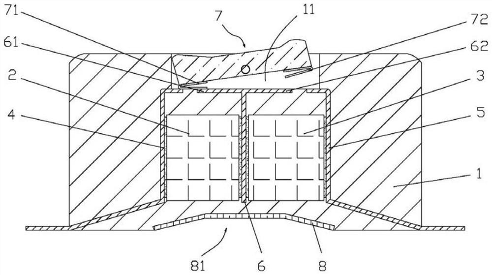
[0033] Such as image 3 The shown Schottky diode with switchable positive and negative poles includes an insulating plastic package 1, and the insulating plastic package 1 is provided with a first Schottky chip 2, a second Schottky chip 3, and a first Schottky chip. The cathode side of the chip 2 is opposite to the cathode side of the second Schottky chip 3, the anode end of the first Schottky chip 2 is connected to the first conductive pin 4 through solder paste, and the anode end of the second Schottky chip 3 The second conductive pin 5 is connected through solder paste.
[0034] A conductive module 6 is connected between the first Schottky chip 2 and the second Schottky chip 3, the conductive module 6 is a T-shaped conductive plate, and the left end of the first Schottky chip 2 and the T-shaped conductive plate is connected by solder paste , the second Schottky chip 3 is connected to the right end of the T-shaped conductive plate through solder paste, the upper end of the ...
Embodiment 3
[0040] Such as Figure 4 The shown Schottky diode with switchable positive and negative poles includes an insulating plastic package 1, and the insulating plastic package 1 is provided with a first Schottky chip 2, a second Schottky chip 3, and a first Schottky chip. The cathode side of the chip 2 is opposite to the cathode side of the second Schottky chip 3, the anode end of the first Schottky chip 2 is connected to the first conductive pin 4 through solder paste, and the anode end of the second Schottky chip 3 The second conductive pin 5 is connected through solder paste.
[0041] A conductive module 6 is connected between the first Schottky chip 2 and the second Schottky chip 3, the conductive module 6 is a U-shaped conductive plate, and the left end of the first Schottky chip 2 and the U-shaped conductive plate is connected by solder paste , the second Schottky chip 3 is connected to the right end of the U-shaped conductive plate through solder paste, the upper end of the...
PUM
 Abstract
Description
Claims
Application Information
 - R&D
- Intellectual Property
- Life Sciences
- Materials
- Tech Scout
- Unparalleled Data Quality
- Higher Quality Content
- 60% Fewer Hallucinations
Browse by: Latest US Patents, China's latest patents, Technical Efficacy Thesaurus, Application Domain, Technology Topic, Popular Technical Reports.
© 2025 PatSnap. All rights reserved.Legal|Privacy policy|Modern Slavery Act Transparency Statement|Sitemap|About US| Contact US: help@patsnap.com