Fan blade metal sealing edge and machining method thereof

A technology of a fan blade and a processing method, which is applied in the field of metal edge sealing of fan blades and its processing, can solve the problems of difficult overall deformation control, large overall deformation of the reinforcement edge, large size of the metal reinforcement edge, etc., so as to improve the overall stress relief effect. , Improve product performance, fix and reliable effect

Pending Publication Date: 2022-05-27
上海涵鲲科技有限公司
View PDF15 Cites 0 Cited by
  • Summary
  • Abstract
  • Description
  • Claims
  • Application Information

AI Technical Summary

Problems solved by technology

[0003] Due to the large size of the metal reinforcement edge, poor overall and local rigidity, and high dimensional accuracy requirements, the traditional machining method has problems such as difficulty in V-shaped groove processing, long cycle, large material consumption, and large overall deformation of the reinforcement edge; Processing by plastic forming / diffusion welding connection method, because there are at least two thermal cycles in the processing process, there is also the problem of difficulty in overall deformation control
[0004] Some processing technologies in the prior art adopt the method of direct forming by laser deposition, and at the same time, the support frame is added in sections during the layer-by-layer accumulation process to increase the rigidity and reduce the deformation, but the support frame used in this method is also made of laser Accumulation will also cause deformation during the forming process, so the deformation cannot be effectively controlled, which will affect the performance of the material; moreover, the surface of the laser forming is relatively rough, and the inner wall of the V-shaped groove still needs to be processed, which cannot effectively reduce the cost

Method used


Image

  • Fan blade metal sealing edge and machining method thereof
  • Fan blade metal sealing edge and machining method thereof
  • Fan blade metal sealing edge and machining method thereof

Examples


Embodiment 1

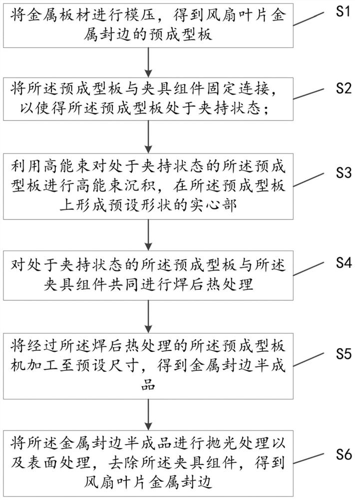
[0042] The present embodiment provides a processing method for metal edge banding of fan blades, such as attached to the instructions Figure 1 As shown, the processing method comprises:

[0043] S1, the metal plate is molded to obtain the preformed plate with metal edge banding of the fan blade;

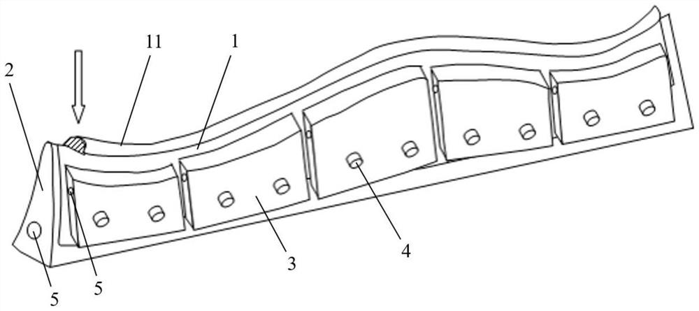
[0044] S2, the preformed plate and the fixture assembly is fixedly connected so that the preformed plate is in a clamping state; wherein the fixture assembly comprises at least one first conformal fixture and a plurality of second conformal fixtures, the inner side of the preformed plate and the first conformal fixture is fixed by a high-strength adhesive connection, the outer side of the preformed plate and the second conformal fixture is fixed by reinforcing the assembly connection;

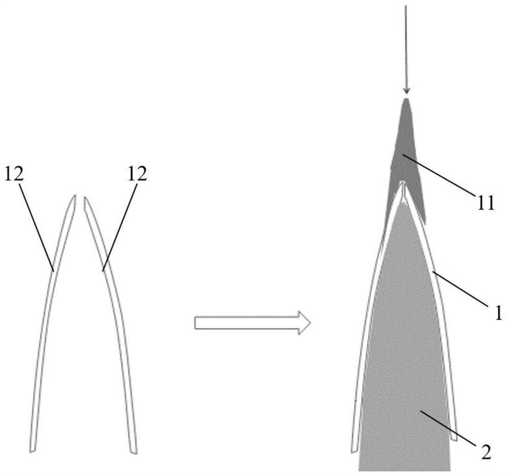
[0045] S3, the use of high-energy beams in the clamping state of the preformed plate for high-energy beam deposition, the formation of a preset shape of the solid part of the preformed plate;

[0046] S4, t...

Embodiment 2

[0086] The metal edge banding of the fan blades of the present embodiment is processed by the following processing method:

[0087] The metal sheet is molded to obtain a preformed plate with metal edges of the fan blade;

[0088] The preformed plate is fixed to the first conformal clamp by high-strength adhesive, and the second conformal fixture is fixed to the outside of the preformed plate by screw joint, and then the U-shaped clamp is used to lock, so that the preformed plate is in the clamping state, and the inner and outer surfaces are fully fitted with the clamping assembly;

[0089] At a laser power of 1500W, at a scanning speed of 1000mm / min and a powder delivery rate of 6g / min, the preformed plate is laser deposited to form a solid part of the preset shape on the preformed plate; at the same time, in this process, the pore diameter of the cold flow channel is set to 8mm, where the cold flow is passed through, and the flow rate is greater than 0.5M / s to prevent the tempera...

Embodiment 3

[0095] The metal edge banding of the fan blades of the present embodiment is processed by the following processing method:

[0096] The metal sheet is molded to obtain a preformed plate with metal edges of the fan blade;

[0097] The preformed plate is fixed to the first conformal clamp by high-strength adhesive, and the second conformal fixture is fixed to the outside of the preformed plate by screw joint, and then the U-shaped clamp is used to lock, so that the preformed plate is in the clamping state, and the inner and outer surfaces are fully fitted with the clamping assembly;

[0098] At 1000W of laser power, at a scanning speed of 600mm / min and a powder feeding rate of 4g / min, the preformed plate is laser deposited to form a solid part of the preset shape on the preformed plate; at the same time, in this process, the pore size of the cold flow channel is set to 6mm, where the cold flow is passed through, and the flow rate is greater than 0.5M / s to prevent the temperature fro...


PUM


Abstract

The invention discloses a fan blade metal sealing edge and a processing method thereof, and the processing method comprises the following steps: carrying out mold pressing on a metal plate to obtain a preformed plate; the pre-forming plate is fixedly connected with the clamp assembly; wherein the clamp assembly comprises at least one first shape follow-up clamp and a plurality of second shape follow-up clamps, and the inner side of the pre-forming plate and the first shape follow-up clamps are fixed through a high-strength adhesive; performing high-energy beam deposition on the preformed plate to form a solid part with a preset shape; performing postweld heat treatment on the preformed plate and the clamp assembly together, and removing the high-strength adhesive through high-temperature volatilization; and then machining the preformed plate to a preset size, carrying out polishing and surface treatment, and removing the clamp assembly to obtain the fan blade metal sealing edge. The first shape follow-up clamp and the second shape follow-up clamp are adopted to be matched with the shape of the preformed plate for clamping, the preformed plate is connected through the high-strength adhesive volatilized at high temperature, shape correction is convenient, machining deformation is effectively restrained, buckling deformation is limited within 1 mm, and the product performance is improved.

Description

Technical field [0001] The present invention relates to the field of fan blade processing technology, in particular to a fan blade metal edge banding and processing method thereof. Background [0002] As one of the key components of the aero engine, the composite fan blade effectively reduces the weight of the aero engine, but because the carbon fiber composite material itself is inferior to the metal in resistance to bird impact and erosion, and it is easy to crack and delaminate during high-speed rotation, the composite fan blade adopts metal reinforcement edge, including the leading edge reinforcement edge and the tail edge reinforcing edge. [0003] Due to the large size of the metal reinforcement edge, the difference in overall and local stiffness, and the high requirements for dimensional accuracy, the traditional machining method has problems such as difficulty in V-shaped groove processing, long cycle, large material consumption, and large overall deformation of the reinf...

Claims


Application Information

Patent Timeline
Patent Type & Authority Applications(China)
IPC IPC(8): B23P15/00
CPCB23P15/00Y02P70/50
Inventor 刘勇
Owner 上海涵鲲科技有限公司
Why Eureka
Try Eureka