
Shading layer, composite film layer and preparation method thereof

A technology of composite film and light-shielding layer, which is applied in the direction of coating, final product manufacturing, sustainable manufacturing/processing, etc. It can solve the problems of increased film stress, cracking, and lower crystal resistivity, etc., to achieve good light-shielding properties , high binding effect

Pending Publication Date: 2022-05-27
IMDETEK
View PDF0 Cites 0 Cited by
  • Summary
  • Abstract
  • Description
  • Claims
  • Application Information

AI Technical Summary

Problems solved by technology

[0004] The preparation of the light-shielding layer on the surface of the CZT crystal requires a very thick film layer (generally greater than 500nm thickness), which will cause the stress of the film layer to increase during the coating process, the bonding force of the film layer will decrease, and the film layer will easily fall off when wiping. cracked
The existing coating technology usually increases the density of the chamber by increasing the temperature of the coating, and reduces the stress by annealing at a high temperature (>200°C) after coating, but the CZT crystal will diffuse from the electrode to the CZT at high temperature, which will cause the crystal Resistivity decreases, seriously affecting crystal performance

Method used


Image

  • Shading layer, composite film layer and preparation method thereof
  • Shading layer, composite film layer and preparation method thereof
  • Shading layer, composite film layer and preparation method thereof

Examples


Embodiment Construction

[0027] In order to make the purposes, technical solutions and advantages of the embodiments of the present invention clearer, the technical solutions in the embodiments of the present invention will be clearly and completely described below with reference to the accompanying drawings in the embodiments of the present invention. Obviously, the described embodiments These are some embodiments of the present invention, but not all embodiments. The components of the embodiments of the invention generally described and illustrated in the drawings herein may be arranged and designed in a variety of different configurations.

[0028] Thus, the following detailed description of the embodiments of the invention provided in the accompanying drawings is not intended to limit the scope of the invention as claimed, but is merely representative of selected embodiments of the invention. Based on the embodiments of the present invention, all other embodiments obtained by those of ordinary ski...


PUM

PropertyMeasurementUnit
thicknessaaaaaaaaaa
transmittivityaaaaaaaaaa

Abstract

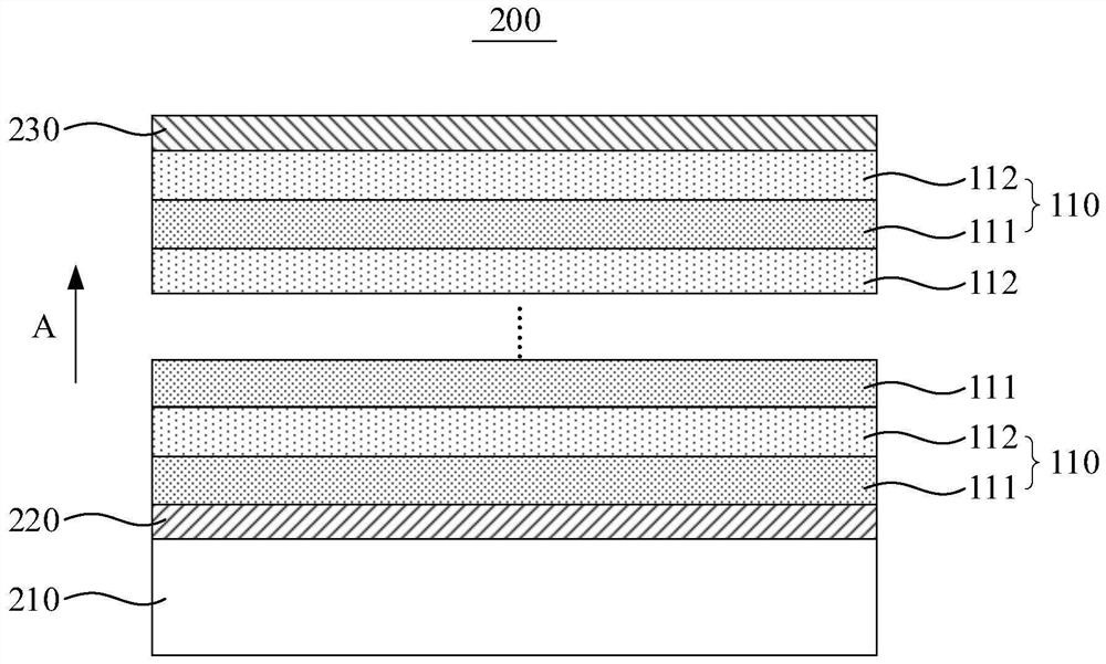
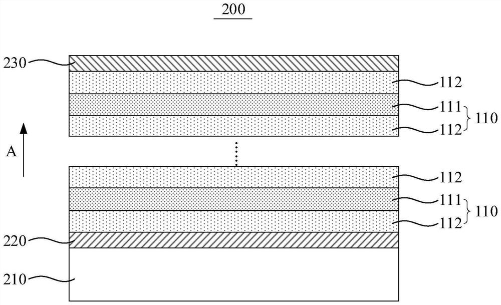
The invention discloses a light shielding layer, a composite film layer and a preparation method thereof, and relates to the technical field of radioactive element detection.The light shielding layer is prepared on the surface of a cadmium zinc telluride crystal and comprises a plurality of first light shielding layers and second light shielding layers which are alternately stacked, and the density of the first light shielding layers is larger than that of the second light shielding layers; the stress of the second shading layer is smaller than that of the first shading layer. The light shielding layer provided by the invention is formed in a mode of alternately laminating the plurality of first light shielding layers and the plurality of second light shielding layers, so that the stress release of the light shielding layer is realized, and the influence on the density of the light shielding layer is reduced to the minimum, so that the light shielding layer can be prepared under a low-temperature condition to obtain a relatively large thickness, and the light shielding property is relatively good; and the binding force with the cadmium zinc telluride crystal is high.

Description

technical field [0001] The invention relates to the technical field of radioactive element detection, in particular to a light shielding layer, a composite film layer and a preparation method thereof. Background technique [0002] With the increasing requirements for air quality, the monitoring of airborne radioactivity in the atmosphere has received widespread attention and attention. The monitoring of airborne radioactivity can be determined by detecting alpha particles emitted when radioactive substances decay. In addition, radon is usually used as a tracer in application fields such as searching for uranium and polymetallic deposits, searching for hidden faults, landslide monitoring, and determination of oil and gas horizon boundaries in the process of oil and gas extraction. Radon is a radioactive gas. Decay also produces alpha particles. The CZT (Cadmium Zinc Telluride) semiconductor detector, as a wipe-resistant alpha particle energy spectrum detector, can be widely ...

Claims


Application Information

Patent Timeline
Patent Type & Authority Applications(China)
IPC IPC(8): H01L31/0216H01L31/118H01L31/18C23C14/18C23C14/30C23C14/54
CPCH01L31/02164H01L31/118H01L31/1832C23C14/30C23C14/542C23C14/18Y02P70/50
Inventor 段志昱汤三奇席守智陈玉霞王宇梁永高孟何丽丽
Owner IMDETEK
Learn More