5G millimeter wave dual-polarized magnetoelectric dipole filtering antenna

A filtering antenna and dual-polarization technology, which is applied in the field of radio frequency communication, can solve the problems of millimeter-wave antenna size reduction, large size, unfavorable millimeter-wave system, etc., and achieve the effect of increasing size and simple structure

Pending Publication Date: 2022-05-31
XIAMEN UNIV
View PDF7 Cites 1 Cited by
  • Summary
  • Abstract
  • Description
  • Claims
  • Application Information

AI Technical Summary

Problems solved by technology

However, in the dual-polarization 5G millimeter wave application, the design of these three feeding methods has certain difficulties. One is that the height of the feeder line is different in the dual-polarization case, and a multi-layer dielectric board is required; The intersection of orthogonal feeders requires the use of jumpers. The third is that the size of the millimeter-wave antenna becomes smaller. The inner conductor of the SMA connector cannot be directly connected and welded. Therefore, how to design a good feed system has become the focus of researchers.
[0004] In recent years, filter antennas have attracted people's attention because of their advantages of high efficiency and low insertion loss; their design methods can be roughly divided into two types. The first one is to cascade the antenna and filter. , which is not conducive to application in millimeter wave systems; the second type adds additional parasitic structures to generate filtering performance, which is more difficult to design

Method used


Image

  • 5G millimeter wave dual-polarized magnetoelectric dipole filtering antenna
  • 5G millimeter wave dual-polarized magnetoelectric dipole filtering antenna
  • 5G millimeter wave dual-polarized magnetoelectric dipole filtering antenna

Examples


Embodiment Construction

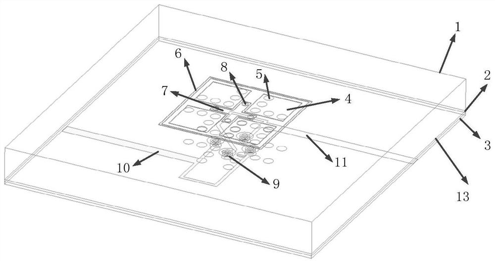
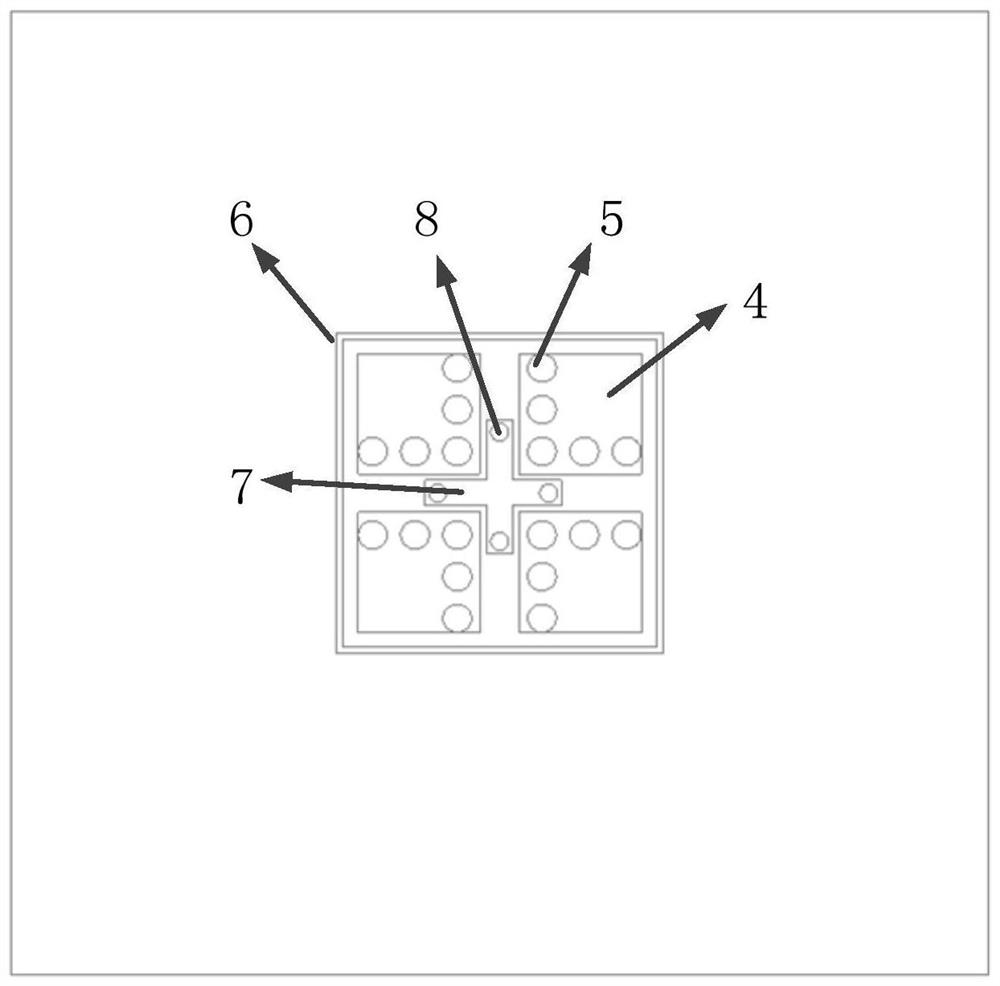
[0032] As shown in Figures 1 to 5, a 5G millimeter-wave dual-polarized magnetoelectric dipole filter antenna according to the embodiment of the present invention, including

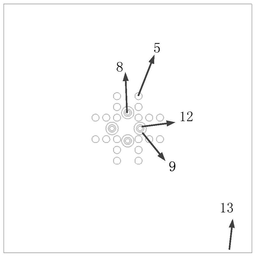
[0034] The lower surface of the top dielectric substrate is printed with a metal ground 13, and four circular slits 9 are loaded on the metal ground 13,

[0036] As shown in FIG. 5, two groups of feeding microstrip lines 10 and 11 are printed on the lower surface of the underlying dielectric substrate, each of which is divided into two groups.

[0040] The present invention can adjust the size of the relevant structure according to the requirements to adapt to the wireless communication system of different frequency bands


PUM


Abstract

The invention discloses a 5G millimeter wave dual-polarization magnetoelectric dipole filtering antenna, and relates to radio frequency communication. Comprising a top dielectric substrate, a bottom dielectric substrate and a middle bonding layer, a radiator structure, a cross-shaped metal patch and an annular metal structure are printed on the upper surface of the top-layer dielectric substrate, the radiator structure is connected to the lower surface of the top-layer dielectric substrate, the cross-shaped metal patch is connected to a feed microstrip line of the bottom-layer dielectric substrate, and the annular metal structure surrounds the radiator structure; a metal ground is printed on the lower surface of the top dielectric substrate, a circular gap is loaded on the metal ground, a circular ring patch is printed on the upper surface of the bottom dielectric substrate, two groups of one-to-two feed microstrip lines are printed on the lower surface of the bottom dielectric substrate, and a branch line is printed at the tail end of one microstrip line; the length of the electric dipole and the height of the magnetic dipole control a low-frequency radiation zero point; and the annular metal structure and the differential circuit control the high-frequency radiation zero point. The structure is simple, the out-of-band rejection level is effectively improved, and the high-frequency out-of-band rejection effect is good. And an extra filter circuit is not introduced, so that a good band-pass filtering effect is realized.

Description

A 5G millimeter-wave dual-polarized magnetoelectric dipole filter antenna technical field The present invention relates to the field of radio frequency communication, specifically relate to a kind of 5G millimeter wave dual-channel with higher roll-off filter characteristic Polarized magnetoelectric dipole filter antenna. Background technique 5G millimeter wave technology is an important technology in 5G applications, because of its large bandwidth, low air interface delay and flexibility. Unique advantages such as flexible air interface configuration, can meet future wireless communication's impact on system capacity, transmission rate and differentiated applications, etc. aspects of demand. Compared with patch antennas and waveguide slot antennas, magnetoelectric dipole antennas have large bandwidth, low cross-polarization and It has the advantages of small back lobe, etc., so it is widely used in wireless communication systems; there are generally three feeding ...

Claims


Application Information

Patent Timeline
IPC IPC(8): H01Q1/38H01Q1/48H01Q1/50H01Q9/16H01Q15/00
CPCH01Q1/38H01Q9/16H01Q1/50H01Q15/0053H01Q1/48Y02D30/70
Inventor 张垚黄楷
Owner XIAMEN UNIV
Why Eureka
Try Eureka