Horizontal well filtration and cleaning simulation combined testing device

A technology of combined testing and simulation testing, which is applied to tools used in natural gas well drilling, completion and cementing engineering, and in the petroleum field, can solve the problems of reducing work efficiency, damaging mud cake on the core surface, and cumbersome problems, so as to improve the convenience of disassembly and reduce the Ring pressure loading pump, the effect of improving work efficiency

Pending Publication Date: 2022-06-03
SINOPEC SSC +1
View PDF0 Cites 0 Cited by
  • Summary
  • Abstract
  • Description
  • Claims
  • Application Information

AI Technical Summary

Problems solved by technology

The operation process is relatively complicated and cumbersome. At the same time, the holder uses special tools to take out the filter loss core and at the same time it will damage the mud cake on the surface of the core. If the operation is not done properly, the mud cake will fall off, resulting in the failure of the entire filter loss process.
[0008] The traditional surrounding rock fluid loss holder is only suitable for conventional core displacement experiments, and cannot simulate the real fluid loss state during drilling
The conventional method is to take out the annular core column after filtration from the holder, and then place it on the weighing platform for measurement. Only by weighing can the fluid loss be fed back and judge whether the thickness of the mud cake reaches the predetermined value. If it does not reach the predetermined value Then the holder needs to be reassembled and the filter loss test is carried out again. Repeated disassembly and assembly of the holder increases the workload, reduces the work efficiency, and easily damages the filter cake

Method used


Image

  • Horizontal well filtration and cleaning simulation combined testing device
  • Horizontal well filtration and cleaning simulation combined testing device
  • Horizontal well filtration and cleaning simulation combined testing device

Examples


Embodiment Construction

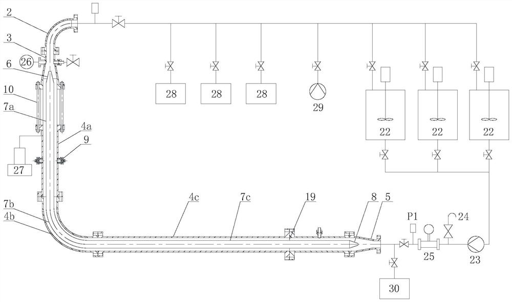
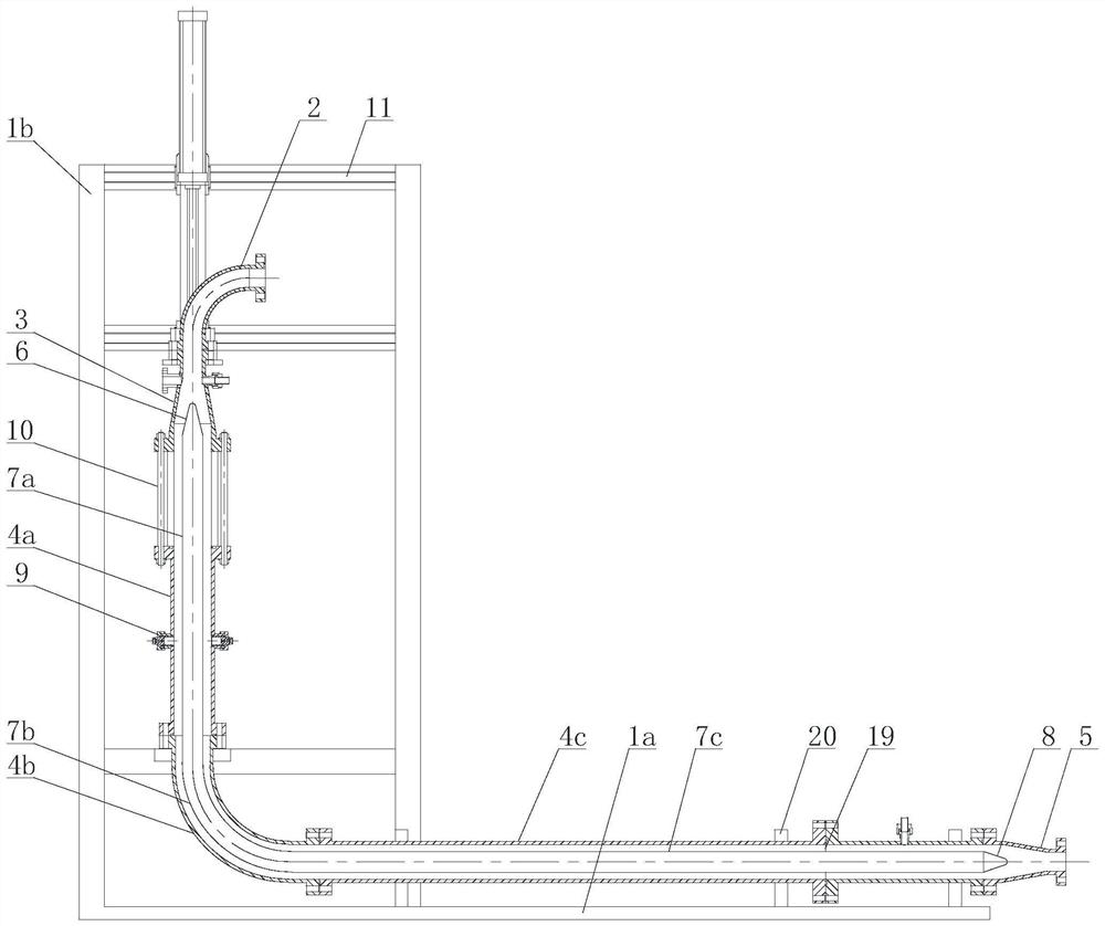
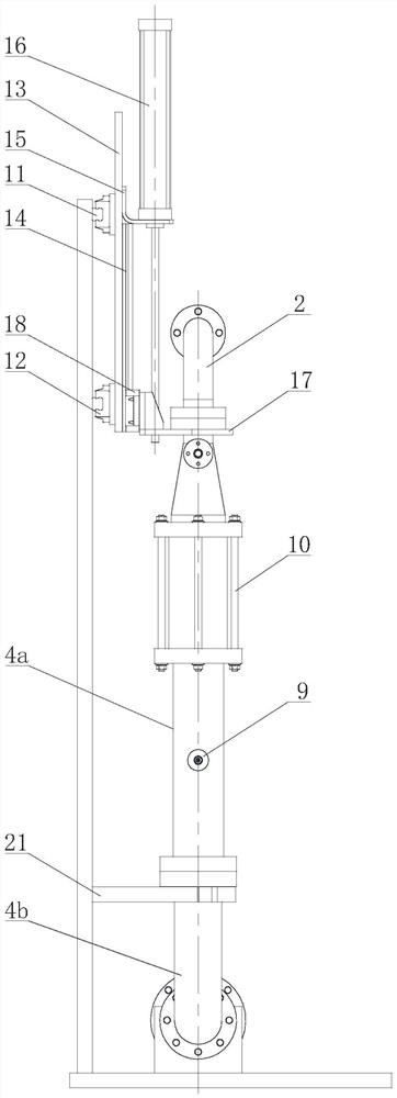
[0029] like figure 1 As shown, the horizontal well fluid loss and cleaning simulation combined test device in the present invention includes a ring rock fluid loss holder, a column rock fluid loss holder and a cleaning simulation test device, and the cleaning simulation test device includes a plurality of sample preparation tanks 22 , the mud pump 23, the simulated test cylinder and the test liquid collection tank 28, the outlet of each sample preparation tank 22 is connected with the inlet of the mud pump 23 through the preparation tank outlet valve respectively, and a safety protection device 24 is installed on the outlet pipeline of the mud pump 23 in turn. , the online flowmeter 25 and the inlet pressure sensor P1 are then connected to the inlet of the lower conical joint of the simulated test cylinder. The simulated test cylinder is L-shaped and fixed on the frame. The upper end of the simulated test cylinder is connected with an upper conical joint, and the upper An onli...


PUM


Abstract

The invention relates to a horizontal well filtration and cleaning simulation combined testing device which comprises a plurality of sample preparation tanks, outlets of the sample preparation tanks are connected with an inlet of a slurry pump through preparation tank outlet valves, an outlet pipeline of the slurry pump is connected with an inlet of a lower conical connector of a simulation testing cylinder, and the simulation testing cylinder is in an L shape and is fixed to a rack. The upper end of the simulation test cylinder is connected with an upper conical joint, an outlet of the upper conical joint is connected with a stewed elbow, and an outlet of the stewed elbow is connected with a plurality of test liquid collecting tanks through a test cylinder outlet pipeline; the simulation test cylinder comprises a cylinder body clamping section, a cylinder body arc-shaped section and a cylinder body flow guide section, and the cylinder body clamping section is provided with a ring rock displacement clamper and a pillar rock displacement clamper. And a simulation sleeve is arranged along the axis of the simulation test cylinder. The device can truly simulate the scouring environment of the underground casing annulus, and the test result is more real and reliable. The device can truly simulate the leakage and scouring environment of the underground casing annulus, and the test result is more real and reliable.

Description

technical field [0001] The invention relates to the technical field of tools for drilling, completion and cementing engineering of oil and natural gas wells, in particular to a combined testing device for fluid loss and cleaning simulation of horizontal wells. Background technique [0002] Drilling fluids are used as working fluids in the drilling process. Drilling fluids are divided into oil-based drilling fluids and water-based drilling fluids. The drilling fluid circulation plays the role of cooling the drill bit, cleaning the bottom of the hole, taking out the cuttings, lubricating the drilling tool, protecting the wall of the hole to prevent collapse, balancing the formation pressure, and transmitting the power needed to break the rock at the bottom of the hole for the power machine at the bottom of the hole. The water in the drilling fluid enters the formation from the hole in the well wall, which is called water loss. At the same time of water loss, the clay particles...

Claims


Application Information

Patent Timeline
IPC IPC(8): E21B47/005E21B33/13E21B21/08
CPCE21B47/005E21B33/13E21B21/08
Inventor 彭金龙李晓黎刘军康王学海夏龙君贾彦龙韩双艳
Owner SINOPEC SSC
Why Eureka
Try Eureka