
Nickel foil for manufacturing thin film capacitor and manufacturing method thereof

A technology of nickel foil and dielectric, which is applied in the field of electrolytic nickel foil, can solve the problems that are not enough to manufacture thin-film ceramic film capacitors, and achieve the effect of excellent processing efficiency

Pending Publication Date: 2022-06-03
乐天能源材料公司
View PDF1 Cites 0 Cited by
  • Summary
  • Abstract
  • Description
  • Claims
  • Application Information

AI Technical Summary

Problems solved by technology

However, according to this invention, the average surface roughness (Ra) is only reduced to about 0.1 μm, which is still not enough to manufacture film type ceramic film capacitors

Method used


Image

  • Nickel foil for manufacturing thin film capacitor and manufacturing method thereof
  • Nickel foil for manufacturing thin film capacitor and manufacturing method thereof
  • Nickel foil for manufacturing thin film capacitor and manufacturing method thereof

Examples


preparation example Construction

[0043] Preparation of Electrolytic Nickel Foil

[0044] The electrolytic nickel foil may be prepared by electrolytic plating with an electrolytic solution containing a nickel ion precursor, a pH buffer, and a roughness control agent and having a pH of 1 to 5.

[0045] The content of the nickel ion precursor of the electrolytic solution is about 400 g / L to 600 g / L relative to the total volume of the electrolytic solution, and within the above ranges, the electrolytic nickel foil is excellent in surface roughness and gloss. The nickel ion precursor can be used without limitation as long as it is a precursor used in nickel ion plating, and the nickel ion precursor is preferably selected from the group consisting of nickel sulfate, nickel sulfamate, nickel chloride, and nickel nitrate group. More preferably, nickel sulfate or nickel sulfamate is used.

[0046] The roughness control agent may comprise selected from the group consisting of saccharin, carboxyethyl isothiourea chl...

Embodiment 1

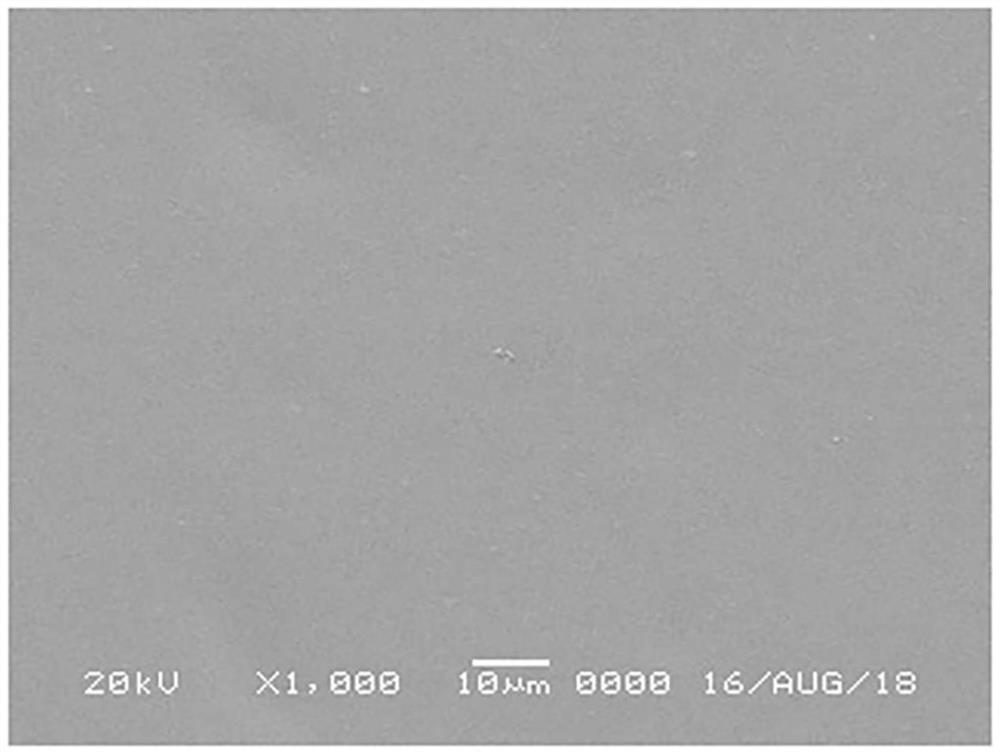
[0073] An electrolyte containing about 450 g / L of nickel sulfate as a nickel ion precursor, about 25 g / L of boric acid as a pH buffer, and about 0.1 g as a roughness control agent was used with an electrolyte containing the following substances at a pH of about 3 / L of saccharin and about 0.8g / L of sodium allyl sulfonate, and at an electrolyte temperature of about 55°C, at about 20A / dm 2 A current density of about 400 s was applied to prepare a nickel foil with a thickness of about 27 μm.

[0074] In the unpolished state, the surface of the prepared electrolytic nickel foil had an arithmetic mean roughness (Ra) of about 0.05 μm, a ten-point mean roughness (Rz) of about 0.19 μm, and a maximum raised height (Rt) of about 0.37 μm, and the 60° specular gloss is about 445GU.

Embodiment 2 to 10

[0076] An electrolytic nickel foil was prepared in the same manner as in Example 1, except that the electrolytic solution and electrolytic conditions shown in Table 1 below were applied.

[0077] [Table 1]

[0078]


PUM

PropertyMeasurementUnit
surface roughnessaaaaaaaaaa
thicknessaaaaaaaaaa
surface roughnessaaaaaaaaaa

Abstract

The present invention relates to an electrolytic nickel foil having a surface roughness Ra of 0.05 [mu] m or less, Rz of 0.2 [mu] m or less, and Rt of 0.5 [mu] m or less on at least one flat surface, and having a glossiness of at least 200 GU as measured by measuring a 60 DEG specular reflection angle.

Description

technical field [0001] The present invention relates to an electrolytic nickel foil, and in particular, to a low roughness and high gloss electrolytic nickel foil capable of manufacturing film capacitors without going through a chemical mechanical polishing (CMP) process, a method for preparing the electrolytic nickel foil, and a method for producing the electrolytic nickel foil. A film capacitor made of this electrolytic nickel foil. Background technique [0002] Semiconductor devices including integrated circuits need to be able to transmit high frequency and high speed signals and operate at low voltages. In order to supply power stably while minimizing noise generation, the system first needs to have low impedance. Therefore, thin-film type ceramic film capacitors with high static capacitance density are used for printed wiring board packaging. [0003] Thin-film ceramic film capacitors are fabricated by depositing a dielectric on a metal foil such as nickel, firing it...

Claims


Application Information

Patent Timeline
Patent Type & Authority Applications(China)
IPC IPC(8): H01G4/33H01G4/30H01G4/008H01G4/12
CPCH01G4/008H01G4/33H01G4/12H01G4/085H01G4/1272H01G4/302
Inventor 宋基德梁畅烈尹相华
Owner 乐天能源材料公司
Learn More