Compression hydraulic buffer structure

A technology of hydraulic buffering and compression holes, which is applied in the direction of liquid shock absorbers, spring/shock absorbers, shock absorbers, etc., can solve the problem that the performance of the shock absorber cannot be responded accordingly, the damping coefficient cannot be changed, and the shock absorption is reduced Performance and other issues, to achieve the effect of improving shock absorption and buffering effect, smooth transition of force value, and increasing damping effect

Inactive Publication Date: 2022-06-07
江苏科曼赛特减振器有限公司
View PDF10 Cites 0 Cited by
  • Summary
  • Abstract
  • Description
  • Claims
  • Application Information

AI Technical Summary

Problems solved by technology

[0003] Existing shock absorbers usually adopt a single-piston structure. The main problem with this type of structure is that after the configuration of the piston valve system is determined, the damping coefficient cannot be changed. When the road conditions change, the performance of the shock absorber cannot be adjusted accordingly. To deal with it, provide the necessary damping force demand, and the job of the shock absorber is to convert kinetic energy into heat energy, so after high-intensity work, the temperature of the oil will rise. As we all know, the viscosity of the oil will increase with the temperature The same is true for the oil in the shock absorber, so when the temperature rises, the damping will actually become smaller, which will seriously reduce the shock absorption performance.

Method used


Image

  • Compression hydraulic buffer structure
  • Compression hydraulic buffer structure
  • Compression hydraulic buffer structure

Examples


Embodiment 1

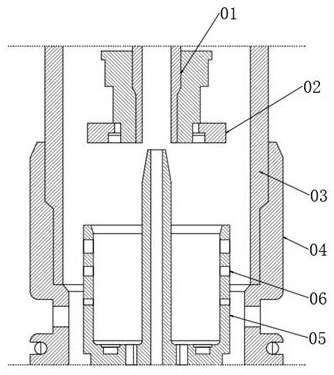
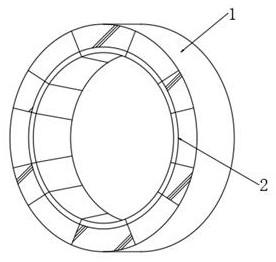
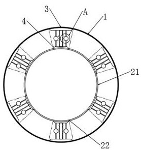
[0041] see Figure 1-3 , a compressed hydraulic buffer structure, including a piston rod 01, a buffer piston 02, an oil storage cylinder 03, a connection base 04 and a hydraulic buffer assembly 05, the buffer piston 02 is installed on the lower end of the piston rod 01, and the oil storage cylinder 03 is installed on the connection Inside the base 04, the hydraulic buffer assembly 05 is installed on the inside of the oil storage cylinder 03 and corresponds to the piston rod 01. The hydraulic buffer assembly 05 is provided with multiple sets of uniformly distributed compression holes 06 from top to bottom, and the compression holes 06 are inlaid and connected with The matching support ring 1, the inner end of the support ring 1 is fixedly connected with the internal variable ring 2, the internal variable ring 2 includes a plurality of staggered shaped segments 21 and external expansion segments 22, the area of ​​the support ring 1 corresponding to the external expansion segment ...

Embodiment 2

[0043] see Figure 4 , between the inner positioning seat 3 and the outer positioning seat 4, a plurality of evenly distributed internal pressure drum covers 7 are arranged, and a pair of symmetrically distributed pull rods 8 are inserted in the internal pressure drum cover 7, and the pull rods 8 are connected to the inner positioning seat 3 respectively. It is fixedly connected with the outer positioning seat 4, the outer end of the thermal expansion rod 5 is also sleeved with an elastic heat preservation sleeve 6, the hollow structure is filled with deionized water, and a plurality of water-cooled capsules 9 are arranged in the internal pressure drum cover 7, and the thermal expansion rod 5 After being heated and expanded to a certain extent, the pull rod 8 will be used to pull the internal pressure drum cover 7, thereby squeezing and breaking the water-cooled capsule 9, and triggering the cooling action to cool the oil. The elastic insulation cover 6 can temporarily isolate ...


PUM


Abstract

The invention discloses a compression hydraulic buffer structure, and belongs to the technical field of shock absorbers, a plurality of groups of compression holes with different depths are formed in a hydraulic buffer assembly, so that compression buffer can be performed when impact force is encountered, and oil can pass through different combinations of holes to be changed into single holes from original multi-holes, so that the impact force is reduced, and the service life of the hydraulic buffer assembly is prolonged. Different from an existing shock absorber adopting an external buffer block structure, the shock absorber can provide a larger supporting force value interval and smoother force value transition, meanwhile, the mode that a supporting ring is embedded in a compression hole is adopted, when the oil temperature rises, an internal thermal expansion rod can be heated to expand, so that an external expansion section is jacked open to expand, and the shock absorption effect is improved. Compared with an existing shock absorber, the large-impact shock absorber has the advantage that the shock absorption and buffering effect under the large-impact working condition can be obviously improved.

Description

technical field [0001] The invention relates to the technical field of shock absorbers, in particular to a compression hydraulic buffer structure. Background technique [0002] The shock absorber is used to suppress the shock when the spring rebounds after absorbing the shock and the impact from the road. It is widely used in automobiles to accelerate the attenuation of frame and body vibrations and improve the ride comfort of automobiles. When passing through uneven roads, although the shock-absorbing spring can filter the vibration of the road surface, the spring itself will reciprocate, and the shock absorber is used to suppress this spring jumping. [0003] Existing shock absorbers usually adopt a single-piston structure. The main problem with this type of structure is that after the configuration of the piston valve system is determined, the damping coefficient cannot be changed. When the road conditions change, the performance of the shock absorber cannot be adjusted ...

Claims


Application Information

Patent Timeline
Patent Type & Authority Applications(China)
IPC IPC(8): F16F9/19F16F9/34F16F9/48F16F9/512F16F9/52F16F9/42F16F9/32
CPCF16F9/19F16F9/34F16F9/48F16F9/512F16F9/526F16F9/42F16F9/3235F16F9/3264
Inventor 姜太云张权
Owner 江苏科曼赛特减振器有限公司
Why Eureka
Try Eureka