
Energy-saving and environment-friendly chemical waste gas spraying equipment

An energy-saving and environmental-friendly spraying equipment technology, which is applied in the direction of lighting and heating equipment, gas treatment, heat exchanger type, etc., can solve the problems of affecting the treatment efficiency, no use of waste gas heat energy, insufficient energy conservation and environmental protection, etc., and achieves a convenient and efficient treatment process. High efficiency, efficiency and environmental protection effect

Pending Publication Date: 2022-06-17
南通久奇环保节能工程有限公司
View PDF0 Cites 2 Cited by
  • Summary
  • Abstract
  • Description
  • Claims
  • Application Information

AI Technical Summary

Problems solved by technology

[0003] However, the existing hygroscopic agents usually used in drying treatment need to shut down the equipment for a long time after a period of use to refill and replace the desiccant, which greatly affects the processing efficiency and increases the cost of raw materials and labor costs. When the existing heat-containing waste gas is treated, the heat energy contained in the waste gas is not utilized, which is not energy-saving and environmentally friendly. Therefore, it is now necessary to design an energy-saving and environmentally-friendly chemical waste gas spraying equipment.

Method used


Image

  • Energy-saving and environment-friendly chemical waste gas spraying equipment
  • Energy-saving and environment-friendly chemical waste gas spraying equipment
  • Energy-saving and environment-friendly chemical waste gas spraying equipment

Examples


Embodiment Construction

[0026] The technical solutions in the embodiments of the present invention will be clearly and completely described below with reference to the accompanying drawings in the embodiments of the present invention. Obviously, the described embodiments are only a part of the embodiments of the present invention, rather than all the embodiments.

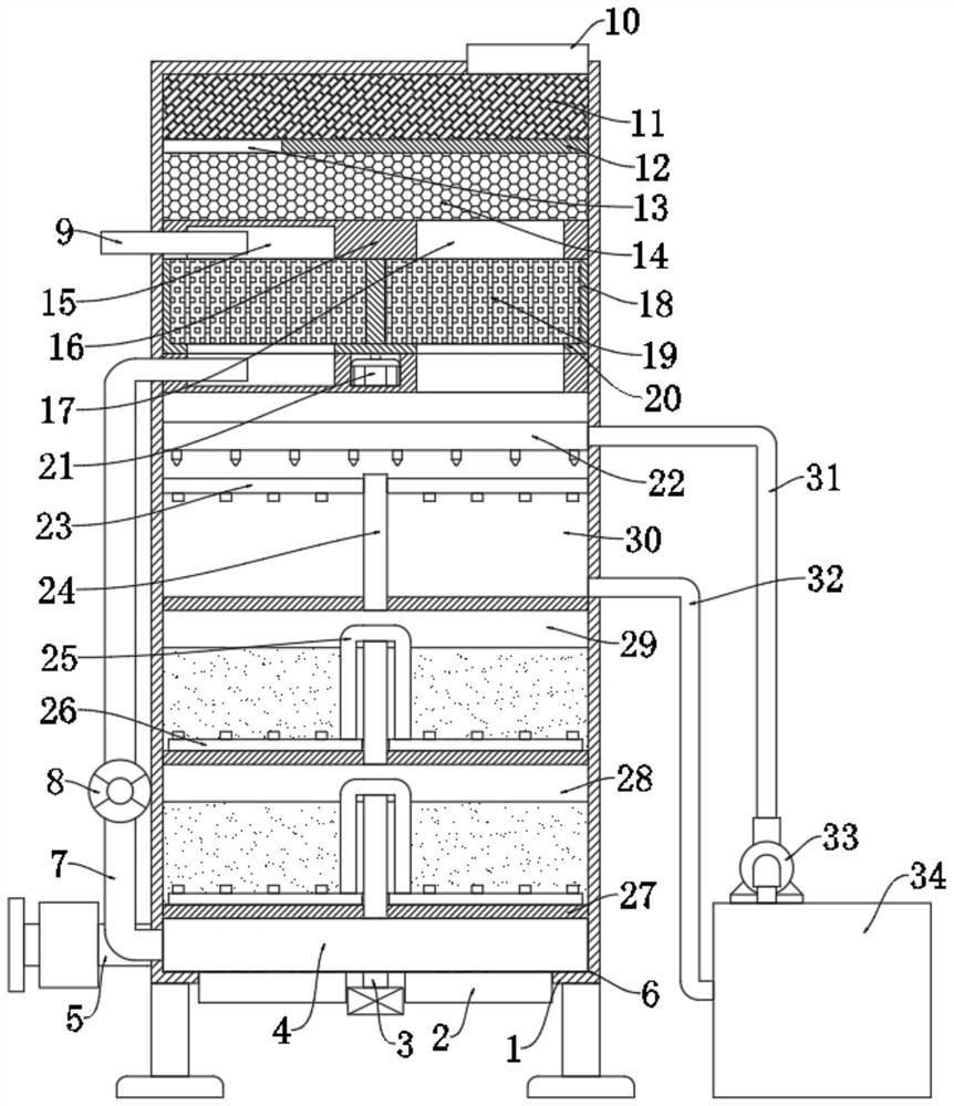
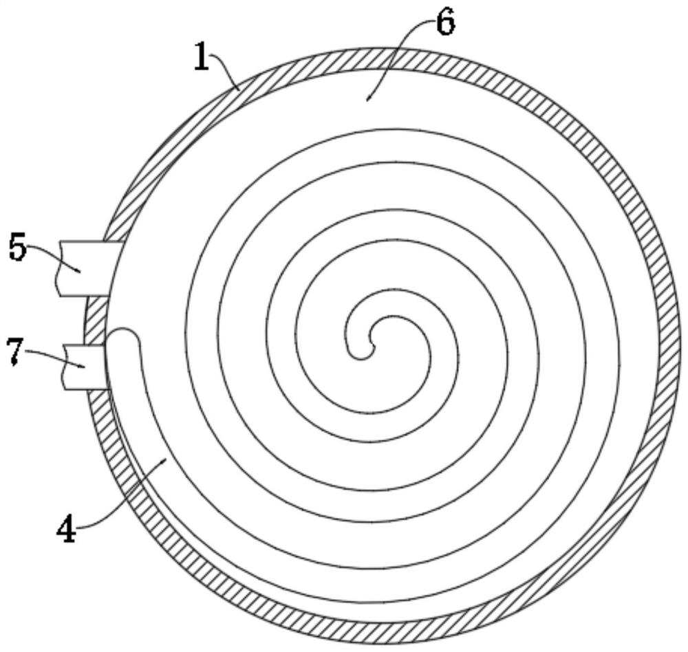
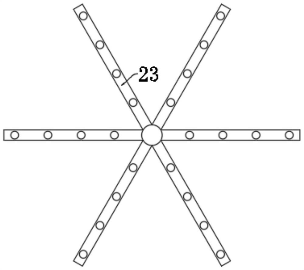
[0027] refer to Figure 1-5 , an energy-saving and environmentally friendly chemical waste gas spraying equipment, comprising a cylinder 1, the interior of the cylinder 1 is provided with three third partitions 27 from bottom to top, and the three third partitions 27 divide the interior of the cylinder 1 into From bottom to top, the heat exchange chamber 6 , the chemical treatment chamber 28 , the recovery water chamber 29 , and the spray chamber 30 , the heat exchange chamber 6 , the chemical treatment chamber 28 , the recovery water chamber 29 , and the spray chamber 30 are all ventilated vertically. The pipes 24 are connected, the chemi...


PUM


Abstract

The invention discloses energy-saving and environment-friendly chemical waste gas spraying equipment which comprises a barrel, three third partition plates are arranged in the barrel from bottom to top, and the three third partition plates divide the interior of the barrel into a heat exchange chamber, a chemical treatment chamber, a water recycling chamber and a spraying chamber from bottom to top. The heat exchange chamber, the chemical treatment chamber, the water recovery chamber and the spraying chamber are communicated with one another through vertical ventilation pipes, two second partition plates are arranged above the spraying chamber, a drying chamber is formed between the two second partition plates, a first partition plate is arranged above the drying chamber, an activated carbon layer and an SCR catalyst layer are arranged on the upper side and the lower side of the first partition plate respectively, and the upper side and the lower side of the first partition plate are communicated with the spraying chamber. A first air passing opening is formed in the first partition plate, and an air outlet pipe is arranged at the top of the barrel. The circulating moisture absorption function can be achieved, the equipment does not need to be shut down, a silica gel drying agent does not need to be frequently replaced, heat energy in waste gas can be effectively utilized, and more energy conservation and environment protection are achieved.

Description

technical field [0001] The invention relates to the technical field of chemical waste gas treatment, in particular to an energy-saving and environment-friendly chemical waste gas spraying device. Background technique [0002] Chemical waste gas refers to the toxic and harmful gas discharged from chemical plants in chemical production. Chemical waste gas often contains many types of pollutants, complex physical and chemical properties, and different toxicity, which seriously pollutes the environment and affects human health. At present, the exhaust gas treatment equipment usually passes the exhaust gas into the chemical treatment liquid, and then absorbs the exhaust gas by spraying the absorption liquid, and then the exhaust gas is dried and then subjected to subsequent catalysis and adsorption treatment. [0003] However, the existing hygroscopic agent usually used in drying treatment needs to shut down the equipment for a long time after a period of use to refill and replac...

Claims


Application Information

Patent Timeline
Patent Type & Authority Applications(China)
IPC IPC(8): B01D53/78B01D53/28B01D53/86B01D53/56B01D53/75F28D7/02F26B21/00
CPCB01D53/78B01D53/28B01D53/04B01D53/8625B01D53/75F28D7/028F26B21/002F26B21/004B01D2253/102B01D2257/80
Inventor 王金渠
Owner 南通久奇环保节能工程有限公司
Learn More