Pretreatment device for boronizing internal chamber of fusion device and application of pretreatment device

A pretreatment device and boronization technology, which is applied in gaseous chemical plating, metal material coating process, coating, etc., can solve the problems of insufficiency and damage to the vacuum environment, simplify the operation steps, and eliminate the belt of pollutants. the effect of entering

Pending Publication Date: 2022-06-21
ENN SCI & TECH DEV
View PDF0 Cites 0 Cited by
  • Summary
  • Abstract
  • Description
  • Claims
  • Application Information

AI Technical Summary

Problems solved by technology

[0004] However, when performing boronization, the plasma discharge of the fusion reaction needs to be suspended, and the boron source needs to be opened to destroy the stable vacuum environment inside the fusion device before injecting it into the fusion device.
In this way, it cannot meet the needs of future fusion devices that will run a very long pulse (that is, quasi-steady state) or run in a steady state discharge

Method used


Image

  • Pretreatment device for boronizing internal chamber of fusion device and application of pretreatment device

Examples


Embodiment 1

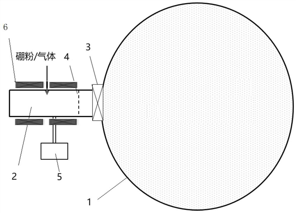
[0057] With the flapper valve closed, helium gas was introduced into the pre-ionization chamber to control the air pressure to 0.5Pa, and then the 13.56MHz radio frequency power supply was turned on to generate stable plasma. After that, boron powder with a purity of 99.99% and a particle size of 50 microns was injected into it, and the injection rate was 100 mg / min.

[0058] Open the plug valve, and through the visible spectrometer installed on the vacuum chamber of the fusion device, obvious boron spectral lines can be seen, indicating that the boron ions have entered the vacuum chamber of the fusion device, and the boronization function has been realized.

Embodiment 2

[0060] When the flapper valve is closed, hydrogen gas is introduced into the pre-ionization chamber, the air pressure is controlled to 0.06Pa, and then the 13.56MHz radio frequency power supply is turned on to generate stable plasma. After that, boron powder with a purity of 99.99% and a particle size of 70 microns was injected into it, and the injection rate was 150 mg / min.

[0061] Open the plug valve, and through the visible spectrometer installed on the vacuum chamber of the fusion device, obvious boron spectral lines can be seen, indicating that the boron ions have entered the vacuum chamber of the fusion device, and the boronization function has been realized.

Embodiment 3

[0063] With the flapper valve closed, helium gas was introduced into the pre-ionization chamber to control the air pressure to 0.05Pa, and then the 13.56MHz radio frequency power supply was turned on to generate stable plasma. After that, boron powder with a purity of 99.99% and a particle size of 90 microns was injected into it, and the injection rate was 100 mg / min.

[0064] Open the plug valve, and through the visible spectrometer installed on the vacuum chamber of the fusion device, obvious boron spectral lines can be seen, indicating that the boron ions have entered the vacuum chamber of the fusion device, and the boronization function has been realized.


PUM

PropertyMeasurementUnit
particle diameteraaaaaaaaaa

Abstract

The invention relates to a boronizing technology of a fusion device, and particularly discloses a pretreatment device for boronizing an internal chamber of the fusion device and application of the pretreatment device. The pre-ionization chamber is arranged outside the fusion device to pre-ionize the boron powder, so that the influence on the stability of conditions such as the vacuum degree in the vacuum chamber of the fusion device is avoided, meanwhile, the introduction of pollutants is completely eradicated, and an existing boron film in the vacuum chamber of the fusion device can be reinforced at any time. After the pre-ionized boron ions enter the vacuum chamber of the fusion device, the inner wall of the vacuum chamber can be boronized while fusion reaction discharging is carried out, an additional boronizing step is not needed, the operation steps are simplified, and the requirement that the fusion device runs very long pulses (namely, the quasi-steady state) or runs in the steady state for discharging in the future can be met.

Description

technical field [0001] The invention relates to the boronation technology of fusion devices, in particular to a pretreatment device for boronation of internal chambers of fusion devices. Background technique [0002] The suppression of plasma impurity ions in the fusion device chamber is one of the major problems that must be solved to achieve controlled thermonuclear fusion. In the physical experiment of the tokamak nuclear fusion device, the high-temperature plasma collides with the inner wall of the device chamber, so that the chamber wall releases various impurities into the plasma in the device chamber, and the impurities will lose the energy of the plasma, thus causing the plasma Huge loss of body energy. Growing a boron film layer on the inner wall of the nuclear fusion vacuum chamber can effectively inhibit the escape of metal impurities, oxygen and carbon impurities in the inner wall, and effectively prevent the inner wall material from being collided as impurities...

Claims


Application Information

Patent Timeline
Patent Type & Authority Applications(China)
IPC IPC(8): C23C16/28C23C16/452
CPCC23C16/28C23C16/452
Inventor 田小让张国松赵鑫吴超孟垂舟
Owner ENN SCI & TECH DEV
Why Eureka
Try Eureka