
Image correction method, device and system and electronic equipment

An image correction and image technology, which is applied in the field of image processing, can solve the problems of low adaptability to the environment, poor alignment image effect, and inability to realize dynamic correction, etc., and achieve the effect of simple correction environment

Pending Publication Date: 2022-07-01
ARCSOFT CORP LTD
View PDF0 Cites 2 Cited by
  • Summary
  • Abstract
  • Description
  • Claims
  • Application Information

AI Technical Summary

Problems solved by technology

[0008] Embodiments of the present invention provide an image correction method, device and system, and electronic equipment to at least solve the problem of the inability to realize dynamic correction between two different cameras in the related art, and low adaptability to the environment, resulting in poor alignment image effect and easily affecting users technical questions of interest

Method used


Image

  • Image correction method, device and system and electronic equipment
  • Image correction method, device and system and electronic equipment
  • Image correction method, device and system and electronic equipment

Examples


Embodiment 1

[0066] According to an embodiment of the present invention, an embodiment of an image correction method is provided. It should be noted that the steps shown in the flowchart of the accompanying drawings may be executed in a computer system such as a set of computer-executable instructions, and, although in A logical order is shown in the flowcharts, but in some cases steps shown or described may be performed in an order different from that herein.

[0067] An embodiment of the present invention provides an image correction method, which can be applied to an image correction system. The image correction system includes: a first image capture device capable of capturing a depth image / infrared image (in this embodiment of the present invention, a depth camera Schematic illustration) and a second image capturing device capable of capturing a visible light image (the embodiment of the present invention is schematically illustrated with a visible light camera). OIS mechanism, AF mec...

Embodiment 2

[0148] An embodiment of the present invention provides an image correction apparatus, and the plurality of implementation units included in the apparatus correspond to each implementation step in the above-mentioned first embodiment.

[0149] Figure 4 is a schematic diagram of an optional image correction device according to an embodiment of the present invention, such as Figure 4 As shown, the image correction apparatus may include: an acquisition unit 41, a first correction unit 43, and a second correction unit 45, wherein,

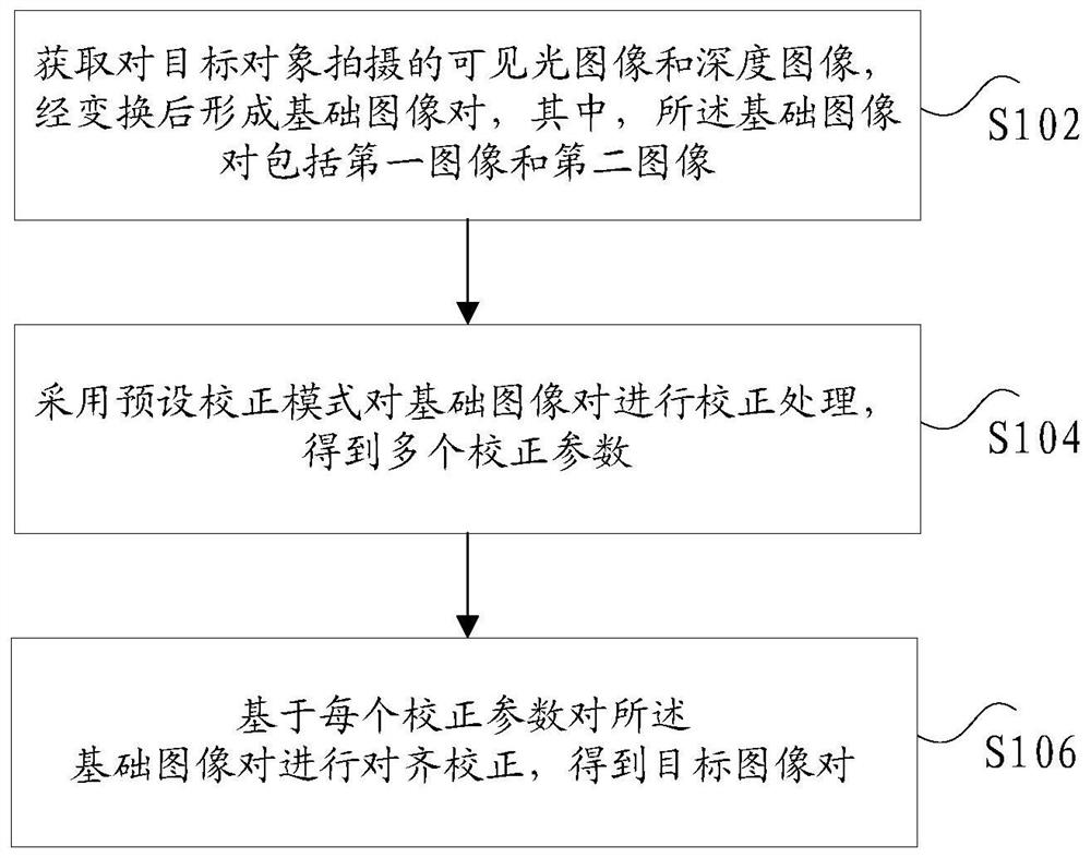
[0150] The acquiring unit 41 is configured to acquire the visible light image and the depth image captured by the target object, and after transformation, form a basic image pair, wherein the basic image pair includes a first image and a second image;

[0151] a first correction unit 43, configured to perform correction processing on the base image pair by using a preset correction mode to obtain a plurality of correction parameters;

[0152] The se...


PUM


Abstract

The invention discloses an image correction method, device and system and electronic equipment. The image correction method comprises the steps that a visible light image and a depth image shot by a target object are acquired, a basic image pair is formed after transformation, and the basic image pair comprises a first image and a second image; performing correction processing on the basic image pair by adopting a preset correction mode to obtain a plurality of correction parameters; and performing alignment correction on the basic image pair based on each correction parameter to obtain a target image pair. The technical problems that dynamic correction between two different cameras cannot be achieved in the prior art, the adaptive environment is low, the image alignment effect is poor, and the use interest of a user is easily affected are solved.

Description

technical field [0001] The present invention relates to the technical field of image processing, and in particular, to an image correction method, device and system, and electronic equipment. Background technique [0002] In related technologies, with the continuous improvement of hardware technology, depth imaging has become more and more accurate, and applications based on depth information have also developed rapidly. At present, common depth imaging methods are mainly divided into three types: binocular stereo imaging and structured light. Imaging and Time of Flight (ToF). [0003] Binocular stereo imaging needs to use two RGB cameras to acquire images at the same time, and then obtain depth information by using the triangulation method through binocular matching. The advantages are low cost, low power consumption and high image resolution. However, since the depth calculation is completely obtained through algorithm calculation, it requires high computing resources, ha...

Claims


Application Information

Patent Timeline
Patent Type & Authority Applications(China)
IPC IPC(8): G06T7/55G06T5/00G06V10/44G06V10/74G06K9/62
CPCG06T7/55G06F18/22G06T5/80G06V10/44G06V10/74G06T7/30G06T2207/20016G06T7/97
Inventor 刘梦晗郁理凤维刚王进
Owner ARCSOFT CORP LTD
Learn More