
Heavy-load chassis rapid displacement driving device

A driving device and chassis technology, applied in fluid pressure actuating devices, printing, printing machines, etc., can solve the problems of reduced production efficiency, harm to human health, and removal of the printing surface, so as to reduce the volume of the cylinder and prolong the service life , damage reduction effect

Pending Publication Date: 2022-07-08
苏州全彩机械设备有限公司
View PDF0 Cites 0 Cited by
  • Summary
  • Abstract
  • Description
  • Claims
  • Application Information

AI Technical Summary

Problems solved by technology

[0003] For the existing printing equipment, when the cup is not correctly inserted into the cup mold, the printing unit of the printing equipment will continue to print. The impact of this is that the ink will adhere to the mold. As we all know, the ink has a strong adhesion ability and After being exposed to UV light, it will quickly cure, causing ink to adhere to the cup mold
When the cup mold is correctly inserted into the cup next time, the ink on the cup mold will contact the inner surface of the cup, causing pollution on the inner surface of the cup. Most of the cups printed by existing printing machines on the market are food-grade plastic cups. will endanger human health
And if you want to clean the ink on the mold, you need to remove the cup mold and use a special cleaning agent to clean it, which is time-consuming and laborious, resulting in a decrease in production efficiency, and it is difficult to meet the current market environment
[0004] The printing unit of the existing printing machine can only manually adjust the chassis through the screw rod. When the cup is not inserted into the cup correctly, the printing unit will continue to print. At this time, the printing unit should stop printing, but it is limited by the response time and the printing unit. Due to the weight of the chassis itself (tens of tons), printing machines on the market cannot quickly move the printing unit of the printing machine away from the printing surface after the cup mold is not correctly inserted into the cup

Method used


Image

  • Heavy-load chassis rapid displacement driving device
  • Heavy-load chassis rapid displacement driving device
  • Heavy-load chassis rapid displacement driving device

Examples


Embodiment Construction

[0022] The technical solutions in the embodiments of the present invention will be clearly and completely described below with reference to the accompanying drawings in the embodiments of the present invention. Obviously, the described embodiments are only a part of the embodiments of the present invention, but not all of the embodiments. The components of the embodiments of the invention generally described and illustrated in the drawings herein may be arranged and designed in a variety of different configurations. Thus, the following detailed description of the embodiments of the invention provided in the accompanying drawings is not intended to limit the scope of the invention as claimed, but is merely representative of selected embodiments of the invention. Based on the embodiments of the present invention, all other embodiments obtained by those skilled in the art without creative work fall within the protection scope of the present invention.

[0023] As shown in the fig...


PUM


Abstract

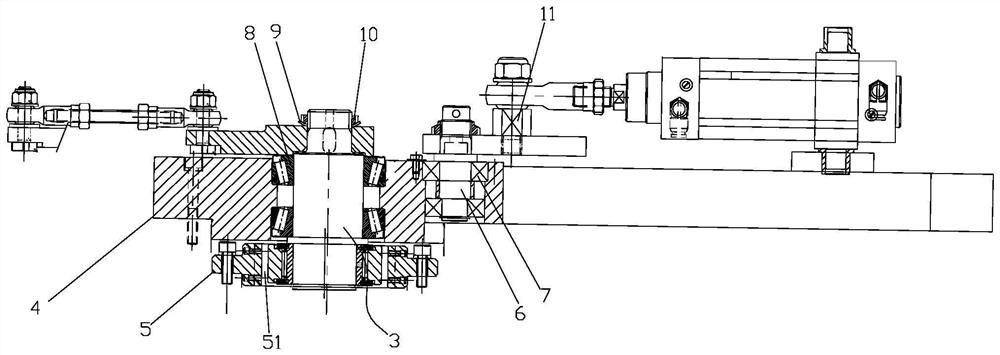
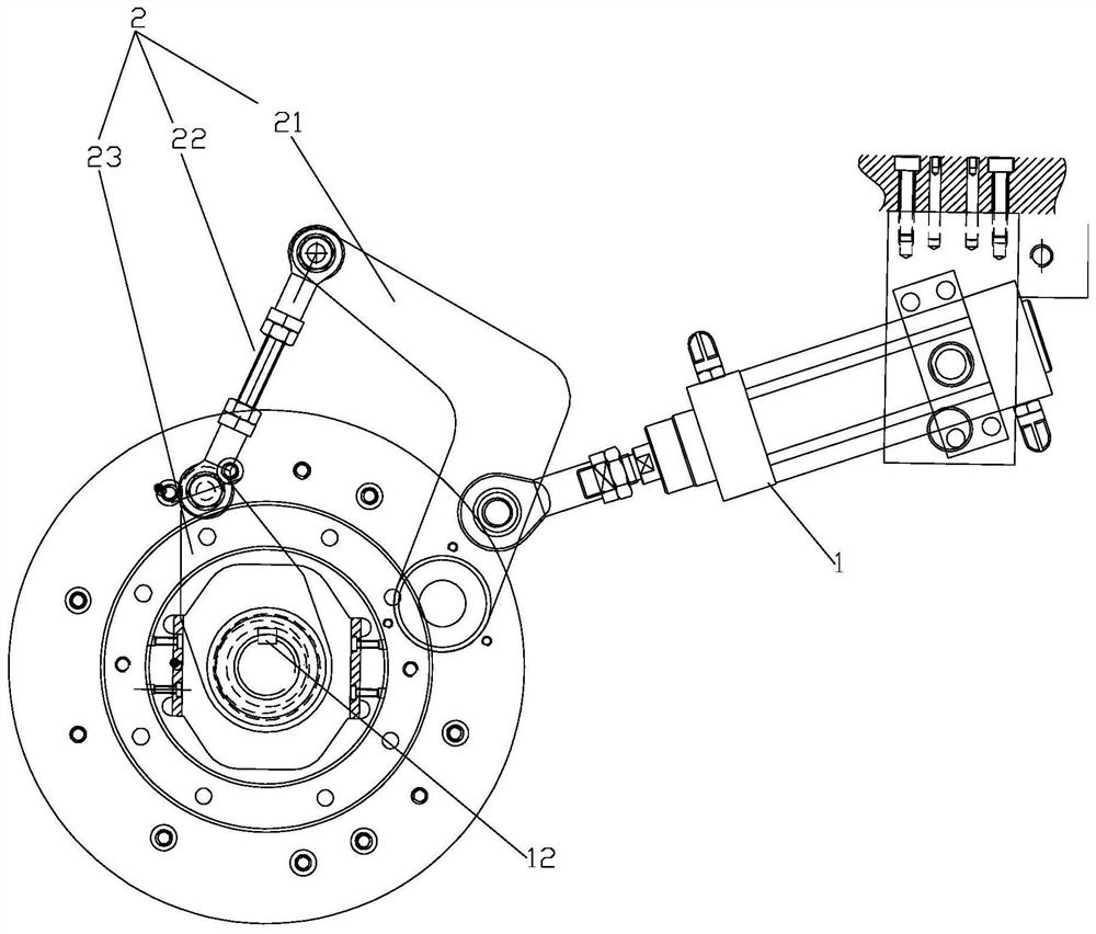
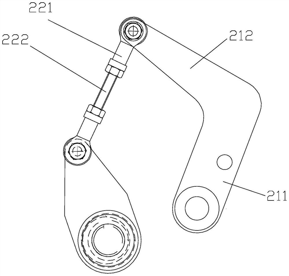
The heavy-load chassis rapid displacement driving device comprises an air cylinder, a connecting rod mechanism, an eccentric shaft, a movable disc and a fixed disc, the fixed disc is located below the movable disc, the output end of the air cylinder is connected with the connecting rod mechanism, one end of the connecting rod mechanism is fixed to the upper end of a rotating shaft, and the lower end of the rotating shaft is installed on the movable disc through a bearing seat; according to the cup mold sleeving mechanism, after a cup mold is not correctly sleeved with a cup, a printing unit of a printing machine can be rapidly moved away from a printing face, damage to an air cylinder can be reduced, and the cup mold sleeving mechanism is high in practicability and high in practicability. The service life of the mechanism is prolonged.

Description

technical field [0001] The invention relates to the field of paper cup printing machines, in particular to a rapid displacement driving device for a heavy-duty chassis. Background technique [0002] Now the fast-moving consumer beverage packaging industry is dominated by plastic cups. With the gradual development of the market and changes in demand, the requirements for curved offset printing machines are getting higher and higher. In the process of changing external demand, the shortages and defects of the cup printing equipment in the current market appear. [0003] For the existing printing equipment, when the cup mold is not properly inserted into the cup, the printing unit of the printing equipment continues to perform the printing function. The impact of this is that the ink will adhere to the mold. As we all know, the ink has a strong adhesion ability, and After exposure to UV light, it solidifies rapidly, causing ink to adhere to the cup mold. When the cup mold is ...

Claims


Application Information

Patent Timeline
Patent Type & Authority Applications(China)
IPC IPC(8): F15B15/06B41F17/14
CPCF15B15/06B41F17/14
Inventor 王福振肖治国
Owner 苏州全彩机械设备有限公司
Learn More