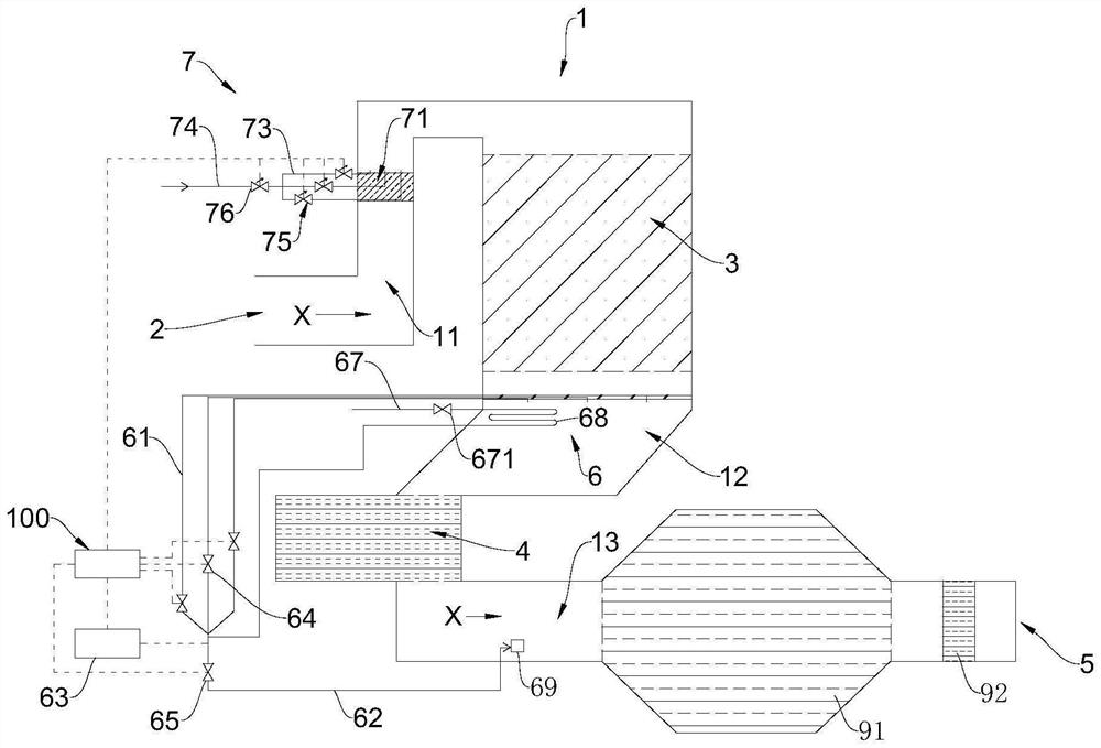
Flue gas extraction analysis and ammonia spraying control system
A flue gas and control valve technology, which is applied in the direction of analysis of materials, sampling, separation methods, etc., can solve the problems of uneven distribution of SCR inlet flow field, inability to adapt to changes in working conditions, and outlet NOx distribution deviation, etc., to improve safety and stability, avoid local excessive injection of ammonia, and reduce the cost of ammonia injection
- Summary
- Abstract
- Description
- Claims
- Application Information
AI Technical Summary
Problems solved by technology
Method used
Image

Examples
Embodiment Construction
[0028] The specific embodiments of the present disclosure will be described in detail below with reference to the accompanying drawings. It should be understood that the specific embodiments described herein are only used to illustrate and explain the present disclosure, but not to limit the present disclosure.
[0029] In the present disclosure, unless otherwise stated, directional words such as "upper and lower" generally refer to "upper, lower", "inner and outer" relative to the direction of gravity when the corresponding component is in use Refers to the "inside and outside" relative to the contour of the corresponding part itself. In the drawings, "A" represents the angle between the first section and the second end, and "X" represents the flow direction of the flue gas. In addition, the terms "first," "second," "third," "fourth," "fifth," etc. used in the present disclosure are for distinguishing one element from another and have no order or importance . Furthermore, ...
PUM
| Property | Measurement | Unit |
|---|---|---|
| Angle | aaaaa | aaaaa |
Abstract
Description
Claims
Application Information