Cutting equipment for machining automobile parts

A technology of auto parts and cutting equipment, which is applied in metal processing equipment, metal processing, shearing machine equipment, etc., can solve the problems of inability to feed steel pipes and reduce the practicability of the device, so as to facilitate transportation, improve practicability, and improve leveling degree of effect

Inactive Publication Date: 2022-07-15
韩树良
View PDF0 Cites 1 Cited by
  • Summary
  • Abstract
  • Description
  • Claims
  • Application Information

AI Technical Summary

Problems solved by technology

[0004] The feeding guide device in the existing cutting equipment is mostly matched with two sets of grooved wheels that are set correspondingly, and then the motor drives the grooved wheels to rotate to make the steel pipe move in translation to realize the feeding work of the steel pipe. Its structure is simple, and the two sets of correspondingly set The sheave is in a fixed position and cannot be adjusted, thus making it impossible to feed pipes of different sizes, reducing the utility of the unit

Method used


Image

  • Cutting equipment for machining automobile parts
  • Cutting equipment for machining automobile parts
  • Cutting equipment for machining automobile parts

Examples


Embodiment

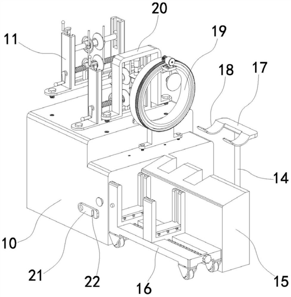
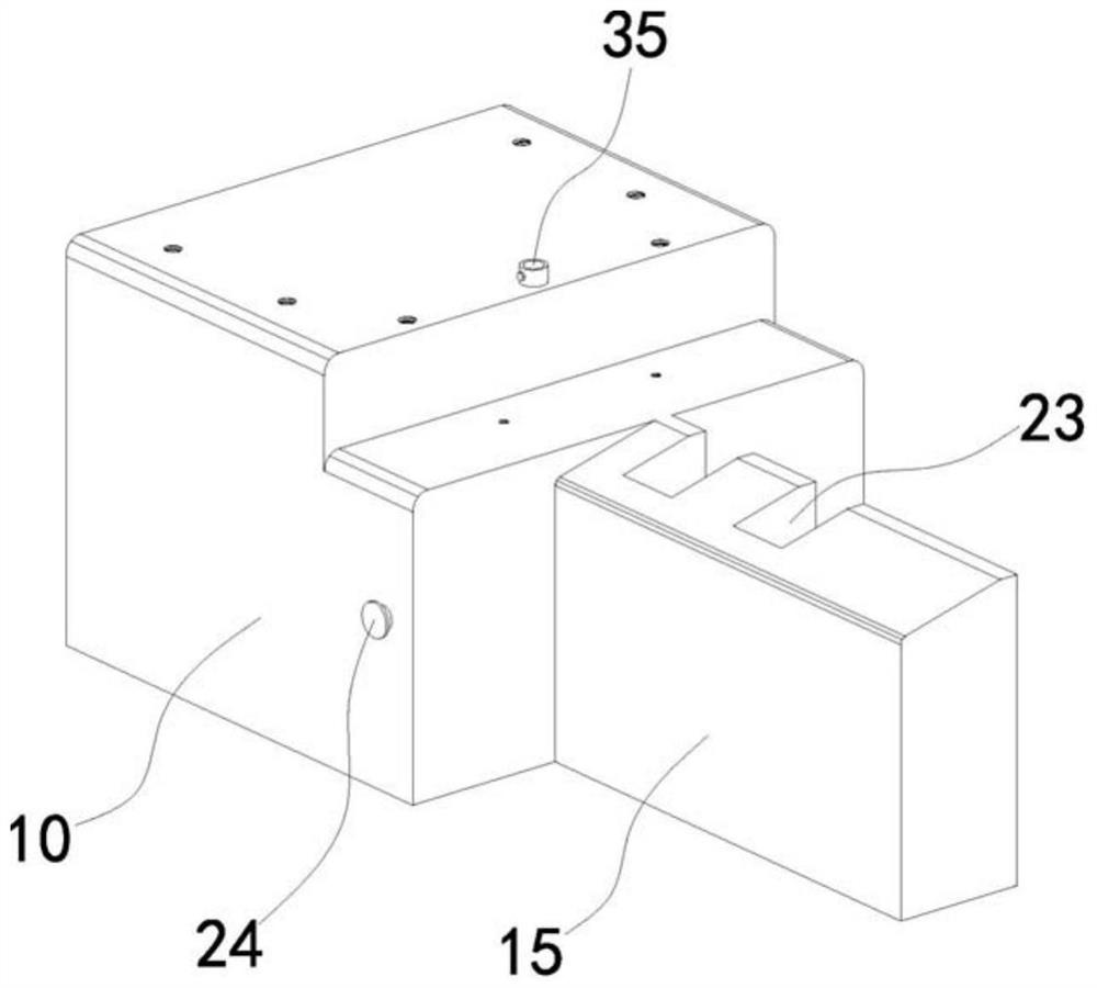
[0034] like Figure 1 to Figure 4 As shown, a cutting device for processing auto parts includes a workbench 10. Two sets of guide assemblies, fixing assemblies and cutting assemblies are arranged on the workbench 10 in sequence. The guide assemblies include a first mounting frame 11. The frame 11 is provided with a two-way screw 36 , two ends of the two-way screw 36 are respectively sleeved with threaded sleeves 39 , and the limit blocks 38 on the peripheral sides of the two sets of threaded sleeves 39 are clamped in the limit chute on the first mounting frame 11 . 37, the upper end of the first mounting frame 11 is provided with two sets of guide chutes 27 opposite to each other, and guide blocks 28 are respectively slidably arranged in the two sets of guide chutes 27, and the two sets of guide blocks 28 are connected by the connecting shaft 29, and the The two ends are respectively sleeved with connecting sleeves 30 , the guide rods 26 on the peripheral side of the two sets ...


PUM


Abstract

The cutting equipment for automobile part machining comprises a workbench, the workbench is provided with two sets of guide assemblies, fixing assemblies and cutting assemblies, each guide assembly comprises a first mounting frame, the two ends of a two-way screw in the first mounting frame are each sleeved with a threaded sleeve, and limiting blocks on the threaded sleeves are clamped in limiting sliding grooves; guide blocks are arranged in the two guide sliding grooves in the first mounting frame, the two guide blocks are connected through a connecting shaft, the two ends of the connecting shaft are sleeved with connecting sleeves, guide rods on the two threaded sleeves are arranged in guide bases on the two connecting sleeves in a penetrating mode, and a first screw in one guide sliding groove is arranged in the guide block in a threaded penetrating mode; and guide wheels are rotationally clamped on the threaded sleeve and the connecting sleeve respectively. And the relative distances of the four sets of guide wheels in the horizontal direction and the vertical direction are adjusted by rotating a two-way screw and a first screw, so that the four sets of guide wheels make contact with the surface of the steel pipe to limit the steel pipe, feeding work can be conveniently conducted on the steel pipes of different sizes, and the practicability of the device is improved.

Description

technical field [0001] The invention relates to the technical field of cutting equipment, in particular to a cutting equipment used for processing automobile parts. Background technique [0002] A car is a powered, non-track-carrying vehicle with 4 or more wheels. Cars are assembled from multiple parts. In the production process of auto parts, some parts are mass-produced as a whole. After these parts are produced, they need to be cut by cutting equipment to obtain parts that meet the size requirements. [0003] For example, the Chinese patent with the patent number of 2020205522564 discloses a cutting device for processing auto parts, including a feeding guide device, a feeding driving device and a cutting device on a workbench. It also includes a lifting and unloading mechanism arranged at the end of the feeding and cutting direction, and the working table has a groove running through the table surface and a collecting bin located inside the working table and communicated...

Claims


Application Information

Patent Timeline
Patent Type & Authority Applications(China)
IPC IPC(8): B23D21/00B23D33/00B23D33/02B23Q7/00B23Q7/08
CPCB23D21/003B23D33/00B23D33/02B23Q7/001B23Q7/08
Inventor 韩树良
Owner 韩树良
Why Eureka
Try Eureka