
Beverage bottling facility

A bottling and beverage technology, applied in the field of beverage bottling facilities, can solve the problems of increasing the complexity of installation and maintenance, complicated installation design, and no disinfection

Pending Publication Date: 2022-07-15
E·F·克林茨基
View PDF0 Cites 0 Cited by
  • Summary
  • Abstract
  • Description
  • Claims
  • Application Information

AI Technical Summary

Problems solved by technology

It's an additional consumable, and besides, it's not popular with consumers
[0027] 3. No hydrogen peroxide (H 2 o 2 ) handles spread stars, the bottles are not fixed by the throat, but use a special design, equipped with special non-standard grippers with plates and rods, for individual placement and support of each container, which complicates the design of the installation , which increases the cost of the bottling process, in addition, it is not sterilized
[0028] 4. Since the conveyor belt is linear and the productivity of the facility is increased by increasing the number of processing stations arranged in a row (in the technical solution there are eight processing stations, i.e. eight containers can be processed simultaneously), this lead to an increase in facility costs
In addition, the dual circuit system greatly increases the complexity of installation and maintenance (changing container formats, repairs, etc.) and most importantly, requires more complex automatic cleaning systems for equipment when changing products (CIP)

Method used


Image

  • Beverage bottling facility
  • Beverage bottling facility

Examples


Embodiment Construction

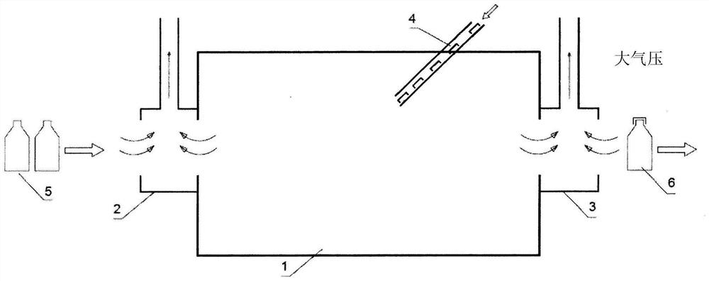
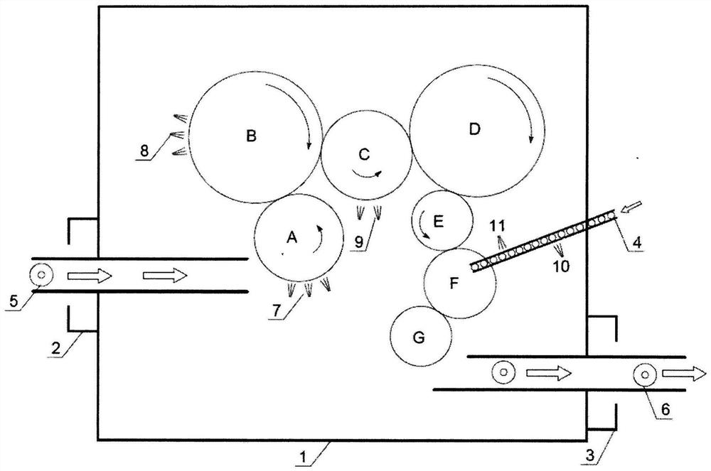
[0039] Composition of proposed objects.

[0040] 1. The outer wall (single) of the facility.

[0041] 2. The hood at the inlet of the monomer (arrows show the movement of the airflow).

[0042] 3. The hood at the outlet of the monomer (the arrows show the movement of the airflow).

[0043] 4. Feed the cap into the monomer (the arrow shows the direction of movement of the cap).

[0044] 5. Feed the empty container into the monomer (arrows show the direction of movement of the container).

[0045] 6. Remove the filled and capped container from the monomer (arrows show the direction of movement of the container).

[0046] 7. The nozzle on Star A treats the vessel with the finely dispersed hydrogen peroxide mixture.

[0047] 8. Nozzle on star B to treat container with fine hydrogen peroxide mixture.

[0048] 9. The nozzles on star C treat the containers with hot sterile air immediately before sending them to the product produced on the filling carousel D.

[0049] 10. At the...


PUM


Abstract

The invention relates to a device for filling and closing containers, bottles or other containers in a sterile environment. The beverage bottling facility of the present invention is a sterile non-sealed isolator filled with a sterilization mixture containing hot air and atomized finely dispersed hydrogen peroxide H202, i.e., hydrogen peroxide vapor. The facility is configured according to the principle of a single-shell isolator shell and operates continuously. An air aspirator housing is provided at the container inlet and the container outlet that causes a controllable movement of the sterilising medium internally and provides a continuous entrainment effect. The inner wall of the container is directly treated with hot sterile air before the container is filled with the product, and the inner wall of the cover is directly treated with hot sterile air before the inner wall of the cover is closed. Prior to filling, the interior of the container is flushed directly with jet-type hot sterile air to remove residues of peroxides. The interior of the cover also needs to be flushed with jet-type hot sterile air. Rinsing of the hot sterile air is performed by a nozzle mounted within the housing along the path of the container and lid. The technical result is that the filling and closing process is more reliable and simpler.

Description

technical field [0001] The present invention relates to an apparatus for filling and closing containers, bottles or any other container in a sterile environment. Background technique [0002] In the first facility, containers are filled and capped in non-sterile equipment, then the shaped containers are moved to a "clean room" with at least one filling machine and one capping machine. [0003] In addition, "usual" aseptic filling lines include: [0004] - starting from a blank or preform of thermoplastic material, forming the container; [0005] - chemical sterilization of shaped containers or preforms; [0006] - Filling and capping of filling containers, which must be done in a clean room. [0007] A "clean room" refers to a controlled contamination room containing all filling equipment, both the technical area where the containers are effectively filled / closed, and the auxiliary area where the mobile equipment of the filling / capping machine operates. [0008] The main...

Claims


Application Information

Patent Timeline
IPC IPC(8): B65B55/04B65B55/06B65B55/10B65B31/00B67C7/00A61L2/00A61L2/22
CPCB67C7/0073B67C2003/228B65B55/10B65B55/06A61L2/22A61L2/208A61L2202/11A61L2202/122A61L2202/15A61L2202/23A61L2202/25B65B55/04B65B31/00B67C7/00A61L2/00
Inventor E·F·克林茨基
Owner E·F·克林茨基
Learn More