
Waste screening and cleaning equipment and cleaning method for mold processing factory

A technology for cleaning equipment and processing plants, which is applied to cleaning methods and appliances, chemical instruments and methods, and the removal of solid waste. It can solve problems such as easy injury, increased labor force, and increased economic costs, so as to increase activation energy and improve Derusting effect, avoiding the effect of floating around

Pending Publication Date: 2022-07-19
徐州百惠模具制造有限公司
View PDF9 Cites 0 Cited by
  • Summary
  • Abstract
  • Description
  • Claims
  • Application Information

AI Technical Summary

Problems solved by technology

[0004] The purpose of the present invention is to solve the need for manual or external equipment to derust and clean the oil stains and rust attached to the surface of waste materials in the prior art. Manual cleaning not only increases manual labor, but also in the process of cleaning, the derusting liquid is harmful to the rust. People's hands are easy to cause injury. If they are cleaned by external equipment, the economic cost will be increased. A kind of waste screening and cleaning equipment and cleaning method for mold processing plants is proposed.

Method used


Image

  • Waste screening and cleaning equipment and cleaning method for mold processing factory
  • Waste screening and cleaning equipment and cleaning method for mold processing factory
  • Waste screening and cleaning equipment and cleaning method for mold processing factory

Examples


Embodiment 1

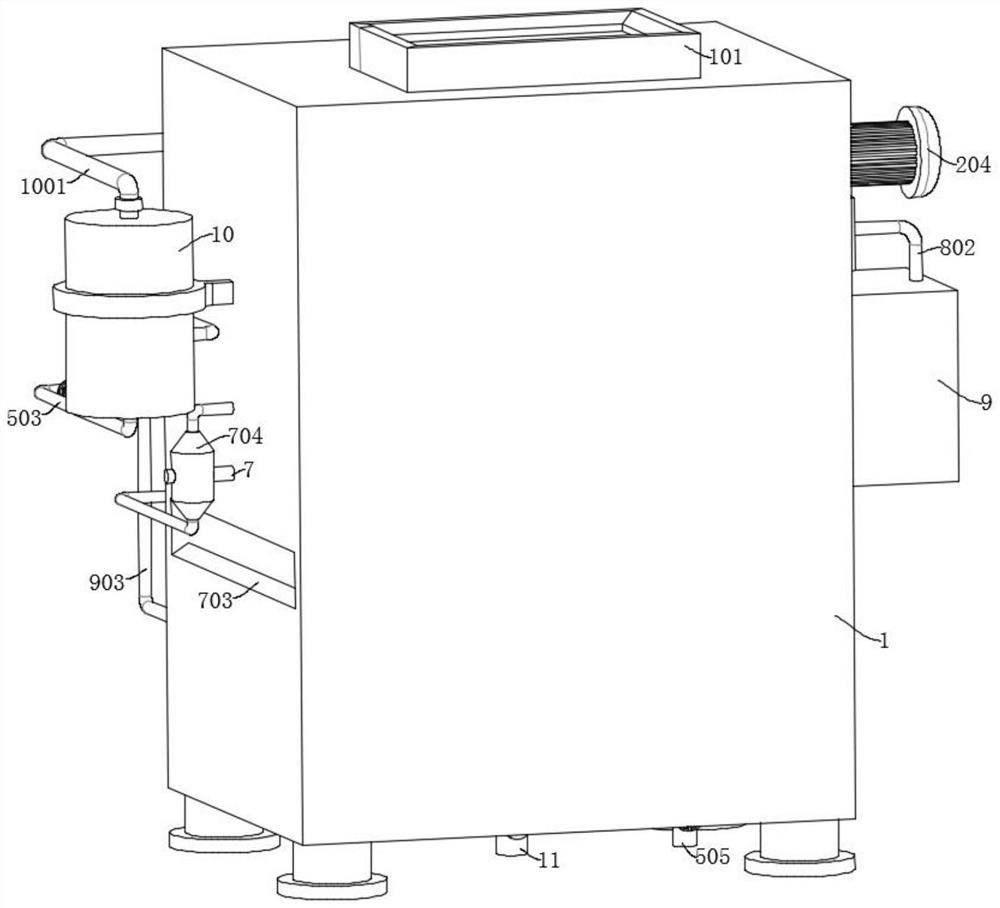
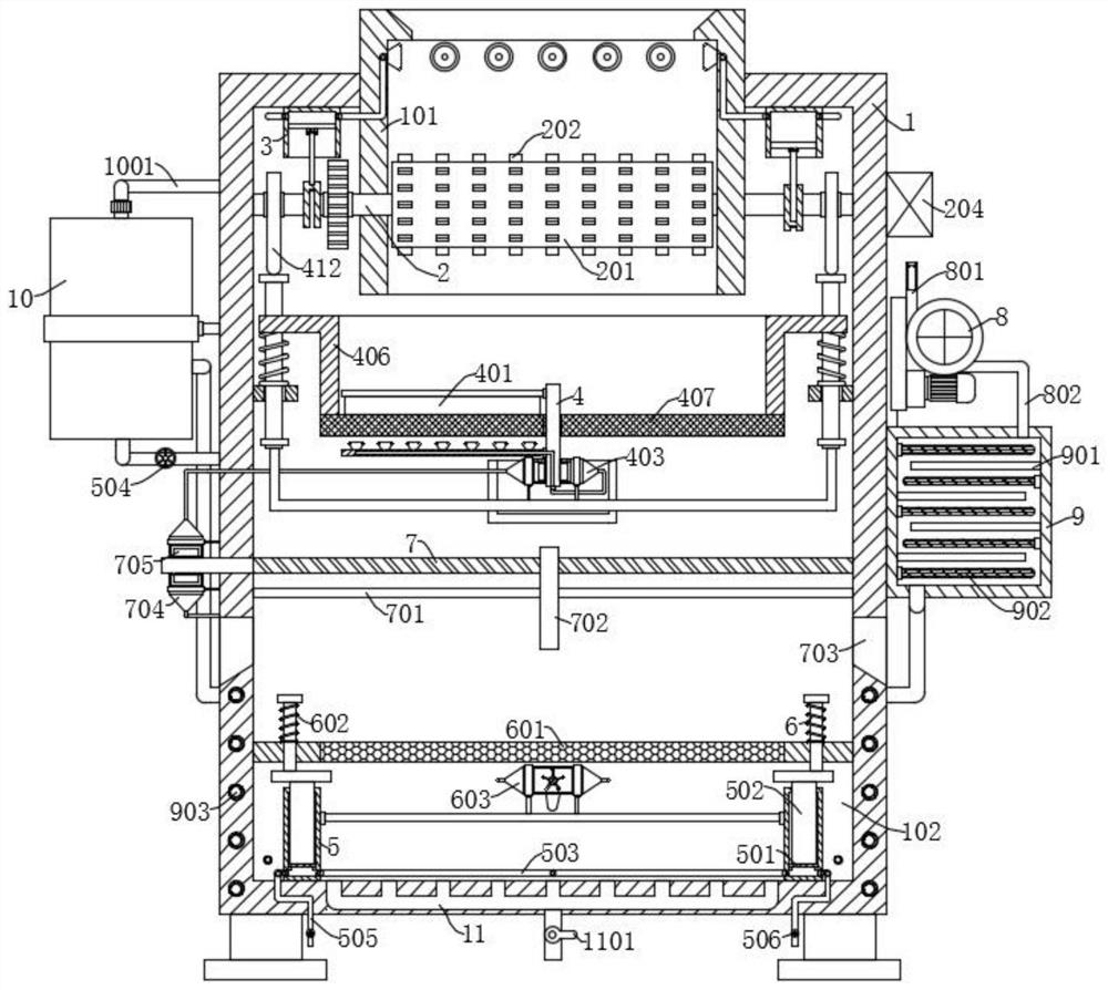
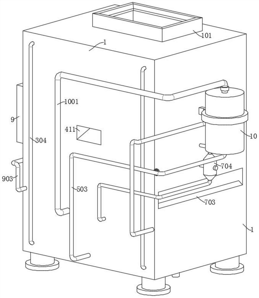
[0043] refer to Figure 1-Figure 10 , a waste screening and cleaning equipment for a mold processing plant, including a box body 1, and also includes: a processing box 101 and two sets of piston assemblies 3, all of which are fixedly connected to the top inner wall of the box body 1, wherein the box body 1 is provided with a cleaning In the cavity 102, the processing box 101 is provided with a crushing mechanism for crushing waste materials; two sets of crankshafts 301 are fixedly sleeved on the crushing mechanism and are rotatably connected with the two sets of piston assemblies 3; the dust collecting cover 303 is fixedly connected to the processing The inner wall of the box 101; the conduit one 302, one end of which is connected to the piston assembly 3, and the other end is connected to the dust collecting hood 303; the conduit two 304, one end of which is connected to the piston assembly 3, and the other end is connected to the cleaning chamber 102; the screening mechanism,...

Embodiment 2

[0056] refer to figure 2 , Image 6 , a waste screening and cleaning equipment used in a mold processing plant, which is basically the same as the embodiment 1. Further, the jacking mechanism includes a sleeve 5 and a piston disc 501 slidably connected in the sleeve 5. The piston disc 501 passes through The support rod 502 is fixedly connected with the support column 6, the sleeve 5 is fixedly connected with the second pipe 505, the sleeve 5 is communicated with the inner cavity of the gas storage tank 10 through the first pipe 503, and the first pipe 503 is connected with a solenoid valve one 504. The second solenoid valve 506 is connected to the second 505 , and the sleeve 5 is fixedly connected to the inner wall of the bottom of the box body 1 .

[0057]The drive assembly that drives the second scraper 702 to move includes a reciprocating screw 7 and a guide rod 701 fixedly connected to the inner wall of the box 1 . The second scraper 702 is slidably connected to the guid...

Embodiment 3

[0060] refer to figure 2 , Figure 10 , a waste screening and cleaning equipment for a mold processing plant, which is basically the same as the embodiment 1, and further, the inner wall of the heating box 9 is provided with multiple sets of interlaced partitions 901, and the multiple sets of partitions 901 are fixedly connected to the heating box. On the inner wall of 9, heating wires 902 are arranged between the adjacent two groups of partition plates 901; when the suction pump 8 extracts the external air through pipeline five 801, and then transports it into the heating box 9 through pipeline six 802 for heating, due to the multiple groups The partitions 901 are staggered and fixedly connected in the heating box 9, so that when the external air enters the heating box 9, the gas flow is S from top to bottom, and is matched with the heating wires 902 between the adjacent two sets of partitions 901. , so that the gas can be fully heated.


PUM


Abstract

The invention discloses waste screening and cleaning equipment for a mold processing factory and a cleaning method, and belongs to the technical field of waste cleaning equipment. Waste screening and cleaning equipment for a mold processing factory comprises a box body and further comprises a processing box and two sets of piston assemblies which are both fixedly connected to the inner wall of the top of the box body, a cleaning cavity is formed in the box body, and a crushing mechanism used for crushing waste is arranged in the processing box; the two groups of crankshafts are fixedly connected to the crushing mechanism in a sleeving manner; according to the waste crushing and screening device, dust generated during waste crushing and screening can be effectively adsorbed and filtered through a Lanx medical rust remover in the cleaning cavity, so that the situation that the dust drifts everywhere and pollutes the environment is effectively avoided, and oil stains and rust adhering to the surfaces of the crushed waste can be decomposed and cleaned; and after oil stains and rust on the waste materials are decomposed and cleaned, the oil stains and the rust can be automatically discharged out of the box body, so that the cleaned waste materials can be conveniently recycled.

Description

technical field [0001] The invention relates to the technical field of waste cleaning equipment, in particular to a waste screening and cleaning device and a cleaning method for a mold processing plant. Background technique [0002] Stamping is to apply external force to sheets, strips, pipes and profiles by means of presses and dies to cause plastic deformation or separation to obtain workpieces of the required shape and size. Therefore, it is necessary to use waste screening and cleaning equipment to screen wastes of different sizes, so as to classify wastes of different sizes, clean them, and then recycle them. [0003] At present, the existing screening and cleaning equipment requires manual or external equipment to remove rust and clean the oil stains and rust attached to the surface of the waste after screening wastes of different sizes. Manual cleaning not only increases manual labor, but also In the process of cleaning, the rust removal liquid is easy to cause damag...

Claims


Application Information

Patent Timeline
Patent Type & Authority Applications(China)
IPC IPC(8): B09B3/00B09B3/35B02C4/08B02C4/30B02C23/08B07B1/34B07B1/42B07B1/46B07B1/52B08B15/04C22B1/00C23G3/00
CPCB09B3/00B02C4/08B02C4/30B02C23/08B07B1/343B07B1/42B07B1/46B08B15/04B07B1/526C23G3/00C22B1/005
Inventor 刘飞
Owner 徐州百惠模具制造有限公司
Learn More