Wear-resistant shaft sleeve coating and preparation method thereof
A technology of coating and shaft sleeve, which is applied in the direction of coating, metal material coating process, etc., can solve the problems of easy peeling of shaft sleeve coating, short service life, and limitation of on-site production efficiency, so as to solve the problem of easy peeling and reduce production The effect of cost and mechanical performance improvement
- Summary
- Abstract
- Description
- Claims
- Application Information
AI Technical Summary
Problems solved by technology
Method used
Image

Examples
preparation example Construction
[0055] The above-mentioned preparation method of the wear-resistant shaft sleeve coating is as follows: the coating raw materials are configured according to the chemical composition of the wear-resistant shaft sleeve coating, and then the reverse synchronous powder feeding method is used to carry out laser cladding, and laser cladding is formed on the surface of the shaft sleeve. layer, and then annealing heat treatment to obtain the wear-resistant bushing coating; the specific steps of the preparation method of the wear-resistant bushing coating are as follows:
[0056] (1) Coating raw materials: use nano-powder to configure according to the chemical composition of the above-mentioned wear-resistant bushing coating, wherein the particle size of the nano-powder is 50-100 nm;
[0057] (2) Laser cladding: send the bushing into the 2 The processing equipment composed of laser, processing machine tool and numerical control equipment uses the reverse synchronous powder feeding met...
Embodiment 1
[0066] (1) Coating raw materials: Nano powder is used to configure according to the chemical composition of the wear-resistant bushing coating, wherein the particle size of the nano powder is 50-100 nm;
[0067] (2) Laser cladding: send the bushing into the 2 The processing equipment composed of laser, processing machine tool and numerical control equipment, the coating material is laser cladding by reverse synchronous powder feeding method. Under the action of the laser, the coating material is clad on the surface of the sleeve to form a 1mm laser cladding layer ; Before laser cladding, preheat the bushing to 200℃, then adjust the power of the laser to 3KW, the laser scanning speed is 200mm / min, the diameter of the laser spot is 5mm, the defocusing distance is 6mm, and the powder feeding rate is 10g / min. min, the overlap ratio is 40%, and the G / R control is 1.3.
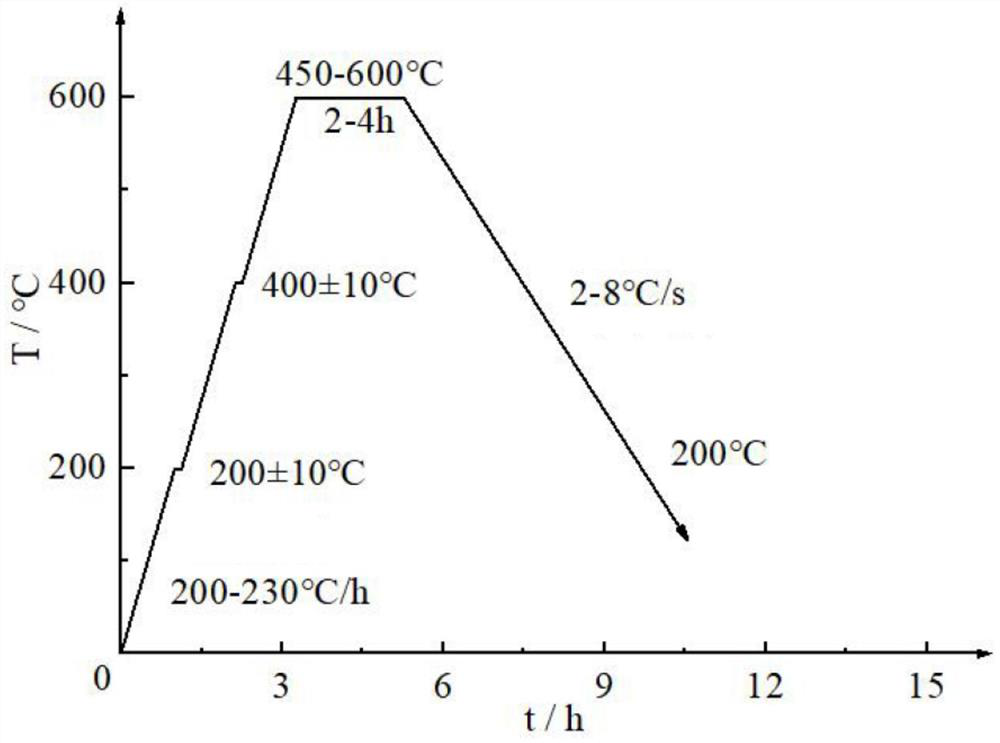
[0068] (3) Annealing heat treatment: First, the shaft sleeve after laser cladding is sent to the heating furnace...
Embodiment 2
[0070] (1) Coating raw materials: Nano powder is used to configure according to the chemical composition of the wear-resistant bushing coating, wherein the particle size of the nano powder is 50-100 nm;
[0071] (2) Laser cladding: send the bushing into the 2 The processing equipment composed of laser, processing machine tool and numerical control equipment, the coating raw material is laser cladding by means of reverse synchronous powder feeding. Before laser cladding, preheat the bushing to 250℃, then adjust the power of the laser to 1.6KW, the laser scanning speed is 120mm / min, the diameter of the laser spot is 3mm, the defocusing distance is 4mm, and the powder feeding rate is 4mm. 8g / min, lap rate 30%, G / R control is 1.5.
[0072] (3) Annealing heat treatment: First, the shaft sleeve after laser cladding is sent to the heating furnace, heated to 200±10°C at a heating rate of 210°C / h, and kept for 10 minutes; then continue to heat up at 200°C / h After heating at a rate of...
PUM
| Property | Measurement | Unit |
|---|---|---|
| thickness | aaaaa | aaaaa |
| particle diameter | aaaaa | aaaaa |
| particle size | aaaaa | aaaaa |
Abstract
Description
Claims
Application Information
 - R&D
- Intellectual Property
- Life Sciences
- Materials
- Tech Scout
- Unparalleled Data Quality
- Higher Quality Content
- 60% Fewer Hallucinations
Browse by: Latest US Patents, China's latest patents, Technical Efficacy Thesaurus, Application Domain, Technology Topic, Popular Technical Reports.
© 2025 PatSnap. All rights reserved.Legal|Privacy policy|Modern Slavery Act Transparency Statement|Sitemap|About US| Contact US: help@patsnap.com