[0049] Example 1
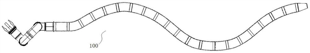
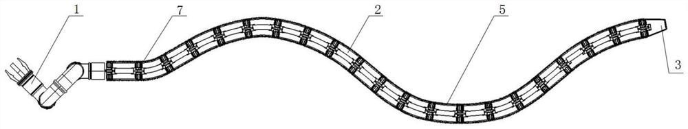
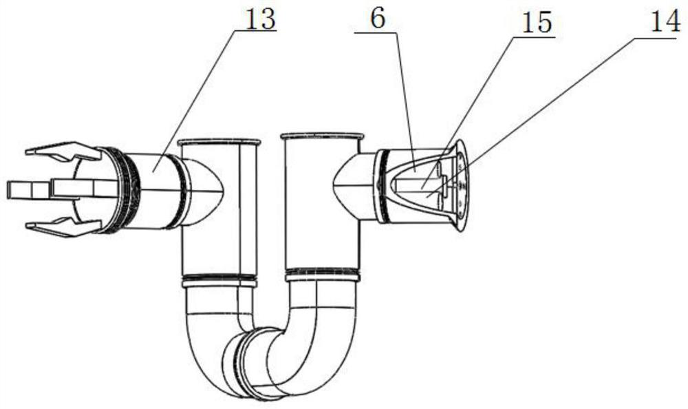
[0050] like Figures 1 to 11 As shown, this embodiment provides an electrically driven rigid-soft coupled water snake robot 100, which mainly includes a snake body skeleton, an electric drive mechanism, a bionic snake skin 5 and a control mechanism 6, and the snake body skeleton includes a snake head 1, a snake body torso 2 and a snake tail connected in sequence. 3. The snake body trunk 2 includes a number of trunk segments 4 connected in sequence, and any trunk segment 4 is a soft coupling structure, which includes a flexible support jacket 41, a variable stiffness spine 42 and multiple groups of elastic expansion and contraction parts 43, multiple groups of elastic expansion and contraction. The parts 43 are distributed on the outer circumference of the variable stiffness spine 42, and the flexible support jacket 41 is covered on the outer circumference of multiple groups of elastic expansion and contraction parts 43; both ends of any elastic expansion and contraction part 43 are connected with an electric drive mechanism, and the electric drive mechanism is used to drive the elastic The telescopic piece 43 is stretched and retracted to drive the torso section 4 to bend; the bionic snake skin 5 is wrapped around the outer periphery of the snake body skeleton; The wagging tail of the snake body skeleton swims, and then achieves an accurate simulation of the "S" shape of the water snake. The above-mentioned variable stiffness electric drive rigidly softly coupled water snake robot 100 has a compact overall structure and a small space occupation area, and can flexibly change the body shape according to the operating environment, and the water snake robot as a whole is in a curved shape in a motion state. Compared with existing underwater robots, tail swing swimming has better flexibility, maneuverability and environmental adaptability, which can meet the task requirements of underwater complex environment operations.
[0051] In this embodiment, any two adjacent torso segments 4 are connected by a connecting joint 7, and the connecting joint 7 includes a connecting rod 71, a first flange and a second flange, and the first flange is arranged on the connecting rod One end of 71 is used to connect the variable stiffness spine 42 of one of any two adjacent torso segments 4, and the second flange is arranged on the other end of the connecting rod 71 to connect the other of any two adjacent torso segments 4. The patient's variable stiffness spine 42. The torso section 4 located at the head of the snake body torso 2 and the snake head 1 are also connected by the connecting joint 7, wherein one of the first flange and the second flange is connected to the snake head 1, and the other is connected to the snake head 1. 2. The variable stiffness spine 42 of the trunk segment 4 of the head; Correspondingly, the trunk segment 4 located at the tail of the snake body trunk 2 and the snake tail 3 are also connected by a connecting joint 7, wherein the first flange plate and the second flange plate One of them is connected to the snake tail 3 and the other is connected to the variable stiffness spine 42 of the torso segment 4 located at the tail of the snake's trunk 2 . As a preferred way, as Figure 5 As shown, the first flange plate and the second flange plate are located at the left and right ends of the connecting rod 71 respectively. Taking the first flange plate as an example, the first flange plate includes a flange disc 72 and a cylindrical sleeve 73, The diameter of the cylindrical sleeve 73 is smaller than that of the flanged disk 72, the cylindrical sleeve 73 is connected to one side of the flanged disk 72, and is arranged coaxially with the flanged disk 72; the structure of the second flanged disk is the same as that of the first method. The flanges are the same, and the cylindrical sleeve 73 on the first flange and the cylindrical sleeve 73 on the second flange face the two ends of the connecting rod 71 respectively to connect with the variable stiffness spine 42, the snake head 1 or the snake tail 3 For example: when the connecting joint 7 connects two adjacent trunk segments 4, the cylindrical sleeves 73 at both ends of the connecting joint 7 are respectively connected with the variable stiffness spines 42 on both sides; and when the connecting joint 7 connects the trunk segment 4 and the snake head 1 , the cylindrical sleeves 73 located at both ends of the connecting joint 7 are respectively connected with the variable stiffness spine 42 and the snake head 1 in the trunk segment 4; Similarly, when the connecting joint 7 connects the trunk segment 4 and the snake tail 3, the two ends of the connecting joint 7 are connected. Cylindrical sleeves 73 are then connected to the variable stiffness spine 42 and the snake tail 3 in the torso section 4, respectively. As a preferred way, the flange disk 72 and the cylindrical sleeve 73 in the first flange disk and the second flange disk are integral structures, the connecting rod 71 is preferably a double-ended stud, and the center of the flange disk 72 is threaded holes for threaded connection with studs.
[0052] In this embodiment, the flexible support jacket 41 is a rubber sleeve with openings at both ends, and the rubber sleeve is cylindrical. After the cylindrical sleeve 73 is connected to the variable stiffness spine 42 in the rubber sleeve, the method of connecting with the cylindrical sleeve 73 The blue disc 72 extends into the rubber sleeve. Here, preferably, the outer diameter of the flange disc 72 is the same or substantially the same as the inner diameter of the flexible support jacket 41. After the assembly is completed, the outer ring of the flange disk 72 and the inner wall of the flexible support jacket 41 can be fitted through interference fit, vulcanized Sealing is achieved by means of gluing or the like, so as to prevent water from entering the inside of the flexible support jacket 41 or the internal parts of the flexible support jacket 41 falling off. The above-mentioned flexible support jacket 41 is a customized rubber material, which is used to assist in the installation of the elastic elastic member 43 and the connection with the connecting joint 7 , and the outer side of the flexible support jacket 41 is connected with the bionic snake skin 5 . The bionic snake skin 5 is preferably a rubber bellows.
[0053] In this embodiment, any flexible support jacket 41 is provided with four groups of elastic elastic members 43, and the four groups of elastic elastic members 43 are evenly distributed on the outer circumference of the variable stiffness spine 42; The auxiliary installation structure is connected to the inner wall of the flexible support jacket 41 , such as by hooking, bonding, etc., and the connection between the elastic stretch member 43 and the inner wall of the flexible support jacket 41 does not affect the telescopic action of the elastic stretch member 43 .
[0054] In this embodiment, four sets of electric drive mechanism integrated housings 8 are provided between any two adjacent torso segments 4, and an electric drive mechanism is installed on both sides of any electric drive mechanism integrated housing 8; There are four sets of electric drive mechanism integrated casings 8 between the snake body torso 2, and an electric drive mechanism is installed on the side of any electric drive mechanism integrated casing 8 close to the snake body torso 2; Four sets of electric drive mechanism integrated casings 8 are arranged between the snake body torso 2 , and an electric drive mechanism is installed on the side of any electric drive mechanism integrated casing 8 close to the snake body torso 2 .
[0055] In this embodiment, any electric drive mechanism includes a controller 9 and two sets of electric telescopic rods 10, the electric telescopic rods 10 are connected in communication with the controller 9, and the controller 9 is in communication with the control mechanism 6; wherein, the controller 9 is provided with A power source 11 capable of supplying power to the corresponding controller 9 and the electric telescopic rod 10 is further configured in the corresponding electric drive mechanism integrated housing 8 . One end of the electric telescopic rod 10 is arranged on the corresponding electric drive mechanism integrated housing 8 , and the other end of the electric telescopic rod 10 penetrates through the flange disc 72 and extends into the flexible support jacket 41 to connect with the corresponding elastic telescopic element 43 . Based on the structural arrangement that each group of electric drive mechanisms includes two groups of electric telescopic rods 10 , and four groups of electric drive mechanisms are arranged between any two adjacent torso segments 4 , any one of them is used to embed (extend) into the flexible support jacket 41 . The outer eaves of the blue disc 72 are symmetrically provided with 8 holes through which the electric telescopic rod 10 passes through, and the holes play a supporting and guiding role for the electric telescopic rod 10 . In actual operation, the electric drive mechanism is not limited to using the electric telescopic rod 10 , but also a push rod equipped with a motor or a hydraulic cylinder.
[0056] In the present embodiment, the elastic telescopic member 43 is preferably a spring, and both ends of the spring are provided with a spring cover 12 , and the electric telescopic rod 10 is directly connected to the spring cover 12 .
[0057] In this embodiment, the variable-stiffness spine 42 is a plastic tube filled with electrorheological fluid, and any variable-stiffness spine 42 is electrically connected to the control mechanism 6, so that the electrorheological fluid in the plastic tube can flow to the direction of the electric field under the action of the electric field. Solid state transformation to achieve variable stiffness spine 42 with controllable stiffness. By changing the electric field strength around the ER fluid, its shear yield stress can be changed. When the shear yield stress increases, the ER fluid undergoes a "solidification" reaction, that is, its stiffness is increased. Based on this principle, the requirement of controllable spine stiffness can be easily achieved, where the spine is rigid, that is, the initial straight state of the snake body. The above-mentioned control mechanism 6 is preferably electrically connected to each variable stiffness spine 42 through cables, and each cable is sequentially stored in the snake body 2 , and each flange disc 72 is also provided with a wire hole for the cable to pass through. The principle of the liquid-to-solid transformation of the electrorheological fluid is in the prior art, and will not be repeated here.
[0058] In practice, the ER fluid can also be replaced by a magnetorheological fluid material, that is, by changing the magnetic field strength around the magnetorheological fluid, its shear yield stress can be changed. When the shear yield stress increases, the magnetorheological fluid occurs. curing" reaction, i.e. increasing its stiffness. Based on this principle, the requirement of controllable spine stiffness can be easily achieved. Here the spine is rigid, that is, the initial straight state of the snake body. The principle of the liquid-to-solid transformation of the magnetorheological fluid is in the prior art, and will not be repeated here.
[0059] In this embodiment, the snake head 1 is preferably a manipulator capable of gripping objects, and the manipulator is connected to the control mechanism 6 in communication. As the main control module of the whole robot, the control mechanism 6 can be set in the manipulator. The manipulator is also equipped with common existing devices such as a manipulator 13, an independent power supply 14 and a wireless signal transceiver 15. The manipulator 13 is mainly used for underwater grasping. When picking up an object, the independent power supply 14 mainly supplies power to the control mechanism 6 and the robotic arm 13 , and the wireless signal transceiver 15 is connected to the control mechanism 6 in communication for sending and receiving signals for the robot to move or grab objects. The above-mentioned manipulator realizes a fixed connection with the first trunk segment 4 of the snake body trunk 2 through the connecting joint 7 . The above-mentioned manipulator and manipulator 13 all adopt the existing structure, and the specific structure and working principle are not repeated here.
[0060] The working principle of the above-mentioned water snake robot will be described in detail below by taking the snake body trunk 2 with 20 trunk segments 4 as an example. Wherein, any two trunk segments 4 have the same structure and can be used interchangeably; any two connecting joints 7 have the same structure and can be used interchangeably.
[0061] like Figure 11 Shown is the bending state of any trunk segment 4. In order to realize this bending state, each group of electric telescopic rods 10 on both sides of the trunk section 4, namely the first electric telescopic rod 101, the second electric telescopic rod 102, the third electric telescopic rod 102, and the third electric telescopic rod 10. The electric telescopic rod 103 , the fourth electric telescopic rod 104 , the fifth electric telescopic rod 105 , the sixth electric telescopic rod 106 , the seventh electric telescopic rod 107 and the eighth electric telescopic rod 108 are all powered on, and the trunk segment is controlled by the controller 9 4. The third electric telescopic rod 103 and the fifth electric telescopic rod 105 at both ends of the upper side are extended, the fourth electric telescopic rod 104 and the sixth electric telescopic rod 106 are retracted, and the second electric telescopic rod 102 and the eighth electric telescopic rod 108 are extended. long, the first electric telescopic rod 101 and the seventh electric telescopic rod 107 are retracted, and the completion Figure 11 The shown spring flexes upwards to effect flexing of the torso segment. The principle of realizing the bending of other trunk segments 4 in all directions is the same as the above-mentioned principle. During the actual movement of the water snake robot, the movement of the water snake robot can be realized by controlling the different trunk segments 4 to bend in different directions through the control mechanism 6 . Since four sets of springs are arranged in any trunk segment 4, the trunk segment 4 can not only bend up and down, but also bend left and right. The specific principle is the same as the above, and will not be repeated here.
[0062]It can be seen that the water snake robot of the technical solution is a new type of variable stiffness electric drive rigid-soft coupled underwater robot based on a soft robot, which is mainly used for object grasping and sample collection in extreme underwater service environments. The water snake robot adopts a rigid-soft coupling structure. The rigid part is mainly reflected in the electric telescopic rod, the integrated shell of the electric drive mechanism, the connecting joint, the flange and other components; the flexible part is mainly reflected in the variable Rigid spine; the soft part is mainly reflected in the rubber material used in the snake body and the bellows material used in the bionic snake skin. The variable stiffness spine adopts the smart material electric/magnetorheological fluid. Taking the magnetorheological fluid material as an example, by changing the magnetic field strength around the magnetorheological fluid, its shear yield stress can be changed. When the shear yield stress increases, the magnetic current The "solidification" reaction occurs when the liquid changes, that is, its stiffness is increased. Based on this principle, the requirement of controllable spine stiffness can be easily achieved, which improves the flexibility of the water snake robot.
[0063] The snake head part described in this technical solution adopts a manipulator. The end of the manipulator is provided with threaded holes and small holes, and is fixedly connected to the head of the snake body through the connecting joint. The connection is stable and reliable. The front end of the manipulator is equipped with a mechanical arm. Adjusting the rotation of the mechanical arm drives the front-end manipulator to adjust the orientation, so as to realize the grasping of underwater objects.
[0064] The water snake robot of this technical solution adopts electric drive as a whole, and each electric telescopic rod can be energized independently. ) are respectively connected with the spring covers (or “spring sleeves”) in the torso sections on both sides. By controlling the extension and contraction of each electric telescopic rod at the same time, the bending of the spring is realized, thereby realizing the tail swing of the snake body. swim. The driving principle is simple and the driving is reliable.
[0065] The connecting joint of the technical solution adopts double-headed studs to realize fixed connection, and the snake head and the trunk segment, the trunk segment and the trunk segment, and the trunk segment and the snake tail are all fixedly connected through the connecting joint, which can ensure the reliability of the overall structure of the water snake.
[0066] The water snake robot of the technical solution is simple in structure, small in size, light in weight, fast in movement, high in flexibility, and strong in maneuverability, and meets the needs of operations in extreme underwater environments.