Fatigue load flexible applying system for aircraft vibration superposition fatigue strength test
A fatigue strength, fatigue load technology, applied in the field of fatigue load flexible application system, can solve the problems of high test cost, difficult implementation, complex technology, etc., to improve reliability and comprehensiveness, improve accuracy and comprehensiveness, structure Well-designed effects
- Summary
- Abstract
- Description
- Claims
- Application Information
AI Technical Summary
Problems solved by technology
Method used
Image
Examples
Embodiment 1
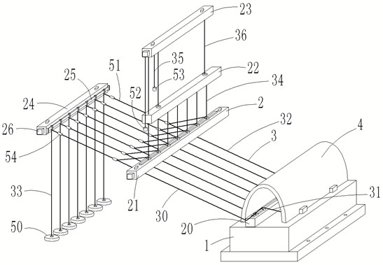
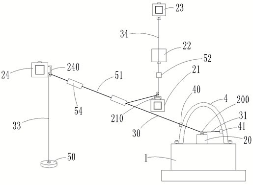
[0038] like figure 1 , 2 The fatigue load flexible application system for aircraft vibration superimposed fatigue strength test shown in , 6 includes test bench 1, support assembly 2 and connection assembly 3; The longitudinal section is an inverted U-shaped structure, six outer loading seats 40 are horizontally distributed on the outer wall of the test piece 4, and six inner loading seats 41 are horizontally divided on the inner wall of the test piece 4 away from the outer loading seat 40;
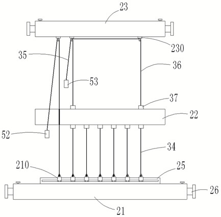
[0039] like figure 1 , 2 , 3 and 6, the support assembly 2 includes an inner fixing beam 20, an outer fixing beam 21, a loading rod 22, a loading fixing beam 23 and a steering fixing beam 24; the inner fixing beam 20, the outer fixing beam 21, the loading rod 22, the loading The fixed beam 23 and the steering fixed beam 24 are parallel to each other, the inner fixed beam 20 is arranged inside the test piece 4 and is fixedly connected with the upper end surface of the test bench 1, and ...
Embodiment 2
[0042] This embodiment differs from Embodiment 1 in that:
[0043] like figure 1 , 8 , 9, both ends of each connecting rubber rope 51 are provided with a quick connector 54, the quick connector 54 includes an outer casing 540, a clamping arc plate 541 and a fastening ring 542, the outer casing 540 is provided with two, two outer casings The bodies 540 are movably connected by threaded sleeves 543, the two outer shells 540 are provided with docking holes 544 on the side away from each other, and eight clamping arc plates 541 are provided, and each clamping arc plate 541 is articulated at two Inside the outer casing 540 and located in the circumferential direction of the docking hole 544 , there are two fastening rings 542 . The tapered holes 5420 are sleeved on the outside of each clamping arc plate 541 on the corresponding side, and a compression spring 545 is provided between the two fastening rings 542 and the inner bottom of the outer casing 540; each clamping arc plate 5...
Embodiment 3
[0045] This embodiment differs from Embodiment 1 in that:
[0046] like image 3 , 4 , 5, the fifth loading cable 34, the seventh loading cable 36 and the loading rod 22 are connected with a connecting seat 37, the connecting seat 37 includes a fixed seat 370 and a sliding sleeve 371, the fixed seat 370 and the loading rod 22 Fixed connection, the fixed seat 370 is provided with a wire cable slot 3700 inside, the sliding sleeve 371 is movably sleeved outside the fixed seat 370, and the inside of the sliding sleeve 371 is provided with a clip 3710 corresponding to the position of the wire cable slot 3700, on the sliding sleeve 371 A tightening screw 372 threadedly connected to the fixing seat 370 is provided through; the inner wall of the sliding sleeve 371 is provided with a guide block 3711 , and the outer wall of the fixing seat 370 is provided with a guide chute 3701 slidably engaged with the guide block 3711 .
PUM
 Abstract
Description
Claims
Application Information
 - R&D
- Intellectual Property
- Life Sciences
- Materials
- Tech Scout
- Unparalleled Data Quality
- Higher Quality Content
- 60% Fewer Hallucinations
Browse by: Latest US Patents, China's latest patents, Technical Efficacy Thesaurus, Application Domain, Technology Topic, Popular Technical Reports.
© 2025 PatSnap. All rights reserved.Legal|Privacy policy|Modern Slavery Act Transparency Statement|Sitemap|About US| Contact US: help@patsnap.com


