
Seismic data sedimentary background removal method and device and electronic equipment

A technology for seismic data and background removal, applied in the field of petroleum geophysical exploration, can solve problems such as relatively large restrictions, easy to "cross-axis, easy to damage seismic data resolution and signal-to-noise ratio, etc., to achieve the effect of reducing impact and fine extraction Effect

Active Publication Date: 2022-07-22
SOUTHWEST PETROLEUM UNIV
View PDF14 Cites 0 Cited by
  • Summary
  • Abstract
  • Description
  • Claims
  • Application Information

AI Technical Summary

Problems solved by technology

The former is to use the stratum frequency characteristics to carry out targeted reconstruction of sedimentary strata, but the horizontal continuity is poor, and it is easy to "cross axis"; the latter is better, but matching pursuit is a greedy algorithm, and each iteration process is Conduct a comprehensive search on the constructed atomic library. Although the existing complex seismic trace analysis and dual-parameter dynamic matching and tracking have improved the operation efficiency, they are not enough to be applied to the 3D data processing of the large work area, and the characteristic parameters are selected during the inversion process. , select a small number of features from multiple parameter features to form a new feature vector. This method requires detailed geological and logging data, and an understanding of the applicable range of various parameters. However, the workload of selecting parameters in this way is large and the practice It is relatively rough and limited by human factors and regional factors; due to the low resolution of seismic data, it is easy to destroy the resolution and signal-to-noise ratio of the original seismic data, and lose thin layer information, so that the spatial prediction of thin sand bodies still has prediction problems. Problems with low reliability of results and strong randomness

Method used


Image

  • Seismic data sedimentary background removal method and device and electronic equipment
  • Seismic data sedimentary background removal method and device and electronic equipment
  • Seismic data sedimentary background removal method and device and electronic equipment

Examples


Embodiment 1

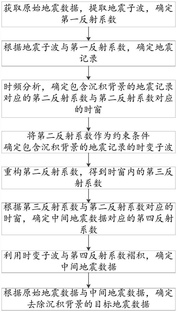
[0066] as attached figure 1 As shown, the method for removing sedimentary background from seismic data includes the following steps:

[0067] Obtain original seismic data, extract seismic wavelets, and determine the first reflection coefficient;

[0068] determining a seismic record according to the seismic wavelet and the first reflection coefficient;

[0069] Determining the seismic records containing the depositional background, performing time-frequency analysis on the seismic records containing the depositional background, and determining the second reflection coefficient corresponding to the seismic records containing the depositional background and the second reflection coefficient. the extent of the time window;

[0070] Using the second reflection coefficient as a constraint, determining the time-varying wavelet of the seismic record containing the depositional background;

[0071] reconstructing the second reflection coefficient to obtain a third reflection coeffi...

Embodiment 2

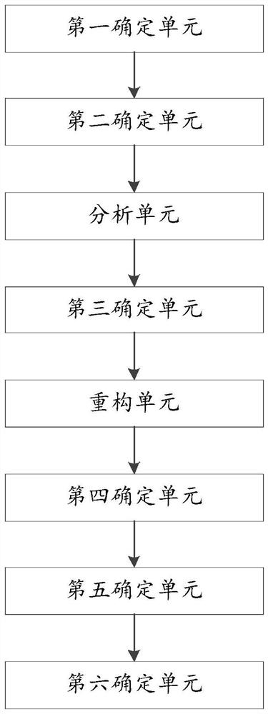
[0143] as attached figure 2 As shown, the seismic data deposition background removal device includes a first determination unit, a second determination unit, an analysis unit, a third determination unit, a reconstruction unit, a fourth determination unit, a fifth determination unit, and a sixth determination unit;

[0144] The first determining unit is used for acquiring original seismic data, extracting seismic wavelets, and determining a first reflection coefficient;

[0145] the second determining unit, configured to determine a seismic record according to the seismic wavelet and the first reflection coefficient;

[0146] The analysis unit is configured to determine the seismic record containing the depositional background, perform time-frequency analysis on the seismic record containing the depositional background, and determine the second reflection coefficient corresponding to the seismic record containing the depositional background and the first reflection coefficient...

Embodiment 3

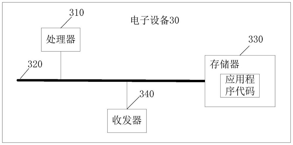
[0176] Based on the same principle as the method shown in the embodiment of the present invention, the embodiment of the present invention further provides an electronic device, as shown in the accompanying image 3 As shown, the electronic device may include but is not limited to: a processor and a memory; a memory for storing a computer program; a processor for executing the method shown in any embodiment of the present invention by invoking the computer program.

[0177] In an optional embodiment, an electronic device is provided, image 3 The electronic device 30 shown includes a processor 310 and a memory 330 . The processor 310 is connected to the memory 330 , for example, through a bus 320 .


PUM


Abstract

The invention provides a seismic data sedimentary background removal method and device and electronic equipment, and the method comprises the steps: obtaining original seismic data, extracting seismic wavelets, and determining a first reflection coefficient; determining a seismic record according to the seismic wavelet and the first reflection coefficient; performing time-frequency analysis, and determining a second reflection coefficient and a time window; time-varying wavelets of the seismic records containing the sedimentary background are determined; reconstructing the second reflection coefficient to obtain a third reflection coefficient in the time window; determining a fourth reflection coefficient according to the third reflection coefficient and the time window; determining intermediate seismic data by using the time-varying wavelet and fourth reflection coefficient convolution; and determining target seismic data of which the sedimentary background is removed. According to the method, the seismic data containing the sedimentary background in the seismic data are restored to the greatest extent by accurately solving the time-varying wavelets and adopting a reflection coefficient inversion mode on the basis of not destroying the original seismic data resolution and signal-to-noise ratio; the method has the advantages of low seismic data demand, low parameter selection and wide applicability.

Description

technical field [0001] The invention relates to the technical field of petroleum geophysical exploration, in particular to a method, a device and an electronic device for removing sedimentary background of seismic data. Background technique [0002] With the development of more and more large-scale and simple-structured oil and gas fields, fewer and fewer simple-structured oil and gas reservoirs can be explored, such as hidden oil and gas reservoirs, thin interbedded oil and gas reservoirs, carbonate oil and gas reservoirs, and shale. Gas and coalbed methane and other complex geological reservoirs have become the main targets of exploration and development. [0003] The existence of depositional background seriously affects the display of effective reflection information. Commonly used methods to remove depositional background include the method of wavelet decomposition and reconstruction of strong reflection stripping and the method of matching and tracing strong reflection...

Claims


Application Information

Patent Timeline
IPC IPC(8): G01V1/28G01V1/30G01V1/36
CPCG01V1/282G01V1/301G01V1/36
Inventor 杨巍张萌张芮刘宏
Owner SOUTHWEST PETROLEUM UNIV
Learn More