Preparation method for metal injection molding of SMT (Surface Mount Technology) carrier plate jig

An injection molding and carrier board technology, which is applied in the field of metal powder injection molding SMT carrier board fixtures, can solve problems such as deformation, uneven size shrinkage, cracking, etc., and achieve the effects of reducing costs, reducing imperfections, and reducing pores

Pending Publication Date: 2022-07-29
ANHUI HAOFANG ELECTROMECHANICS
View PDF0 Cites 0 Cited by
  • Summary
  • Abstract
  • Description
  • Claims
  • Application Information

AI Technical Summary

Problems solved by technology

However, the injection molding process still has certain technical difficulties in the production of products with too large dimensions and too thin thickness, such as problems such as deformation, cracking, and uneven size shrinkage.

Method used


Image

  • Preparation method for metal injection molding of SMT (Surface Mount Technology) carrier plate jig
  • Preparation method for metal injection molding of SMT (Surface Mount Technology) carrier plate jig

Examples


Embodiment 1

[0043] A preparation method for metal injection molding of SMT carrier jig, characterized in that it comprises the following steps:

[0044] 1) Mold preparation steps: According to the product drawing, all the edges without chamfering in the mold are chamfered to C0.2-C0.5, and then increase 0.2mm where the thickness of the glue position in the mold is less than 1.0mm. Thickness allowance. This can effectively avoid the bending phenomenon caused by the small local thickness of the injected embryo.

[0045]2) Prepare metal powder: select SUS301 alloy powder, in which the gas atomized SUS301 alloy powder and the water atomized SUS301 alloy powder are mixed uniformly according to the mass fraction of 5:5 and then used. Among them, the elements contained in the gas and water atomized SUS301 alloy powder are the same as the following elements by mass percentage: C0.1%, Cr18.0%, Ni6.0%, Si1.0%, Mn0.47%, S0.3%, P0.025, oxygen content PPM is 0.03%, and the balance is Fe. The partic...

Embodiment 2

[0068] The difference between Examples 2 and 1 is that the elements contained in the SUS301 alloy powder are the same as the following elements by mass percentage: C0.15%, Cr16.0%, Ni8.0%, Si0.52%%, Mn2. 0%, S0.0005%, P0.025%, oxygen content PPM is 0%, and the balance is Fe. The particle size distribution of these alloy powders was D10: 2.0 μm, D50: 9.5 μm, and D90: 21.0 μm. The degreasing temperature was 127°C, and the degreasing time was 15 hours.

Embodiment 3

[0070] The difference between Examples 3 and 1 is that the elements contained in the SUS301 alloy powder are the same as the following elements by mass percentage: C0.11%, Cr17.0%, Ni7.0%, Si0.62%%, Mn0. 5%, S0.001%, P0.035%, oxygen content PPM is 0.03%, and the balance is Fe. The particle size distribution of these alloy powders was D10: 2.0 μm, D50: 9.5 μm, and D90: 20.0 μm. The degreasing temperature was 113°C, and the degreasing time was 16 hours.

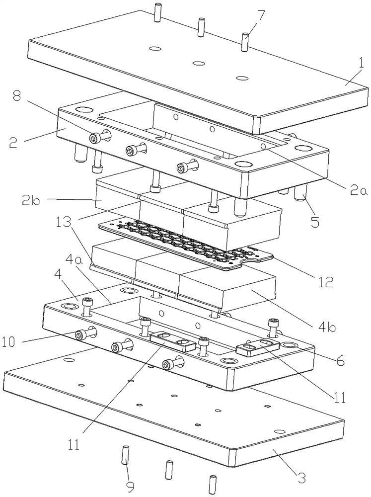
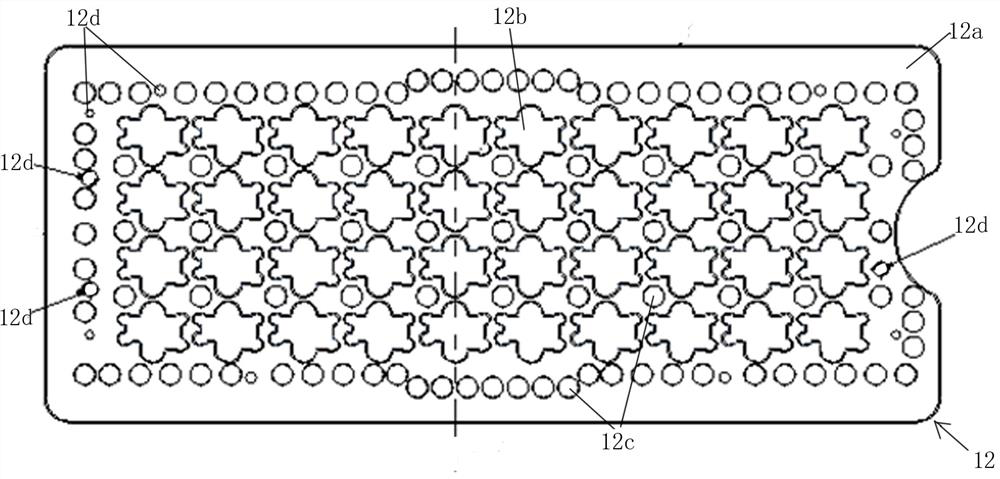
[0071] like figure 1 As shown, a metal injection molding SMT carrier board fixture 12 produced in Examples 1-3 is used, which includes a board body 12a, and a group of connector mounting holes 12b distributed in an array are evenly distributed on the board body 12a, and A group of magnet mounting holes 12c, a part of which are distributed in the array of connector mounting holes 12b, and the other part of the magnet mounting holes 12c are distributed along the length and width of the board 1, in the array of connector mountin...


PUM


Abstract

The invention provides a preparation method for metal injection molding of an SMT (Surface Mount Technology) carrier plate jig. The preparation method is characterized by comprising the following steps: preparing metal powder; blending a binder; preparing feed; injection molding; trimming is conducted; degreasing is conducted; sintering is performed; shaping is conducted; straightening is conducted; performing double-sided grinding; cNC1 processing is carried out; cNC2 processing is carried out; rolling and polishing; performing cleaning; and fully inspecting the size. According to the method, by optimizing parameters such as raw material selection and preparation, mold design, degreasing and sintering processes, products which are good in flatness, free of cracking, good in use performance and meet the requirements of customers are produced, and by combining the metal injection molding (MIM) process and CNC finish machining, the production efficiency is improved, and the cost is reduced.

Description

technical field [0001] The invention relates to the technical field of metal powder injection molding, in particular to a manufacturing method of a metal powder injection molding SMT carrier jig. Background technique [0002] In the SMT processing industry, the welding of PCB boards and electronic components is inseparable from the carrier board fixture. In order to meet the product size consistency and high precision, and at the same time improve production efficiency, very high requirements are placed on the carrier board fixture. . At present, the SMT carrier jig is made of a whole piece of steel, which is processed by a punch, then heat treated, and then CNC finished. High cost and low efficiency. There is an urgent need for a processing technology that can not only meet the accuracy requirements, but also improve production efficiency and reduce costs. [0003] As a near-net-shaping process, metal injection molding process can achieve the requirements of one-time for...

Claims


Application Information

Patent Timeline
IPC IPC(8): B22F3/03B22F3/10B22F3/16B22F9/08C22C38/02C22C38/04C22C38/58C22C38/60
CPCB22F3/03B22F3/1021B22F3/10B22F3/164C22C38/02C22C38/04C22C38/58C22C38/60C22C38/002B22F3/1007B22F9/082B22F2003/166B22F2009/0828B22F2009/0824
Inventor 杜朝晖杨勇吕光辉
Owner ANHUI HAOFANG ELECTROMECHANICS
Why Eureka
Try Eureka