Cement-based 3D printing rock mass model crack filling device and method
A 3D printing and filling device technology, applied in the field of 3D printing and rock mass engineering, can solve the problems of material parameter difference, excessive filling material difference, inaccurate geometric positioning of cracks, etc., achieving a high degree of automation, a wide range of applications, forming great effect
- Summary
- Abstract
- Description
- Claims
- Application Information
AI Technical Summary
Problems solved by technology
Method used
Image
Examples
Embodiment 1
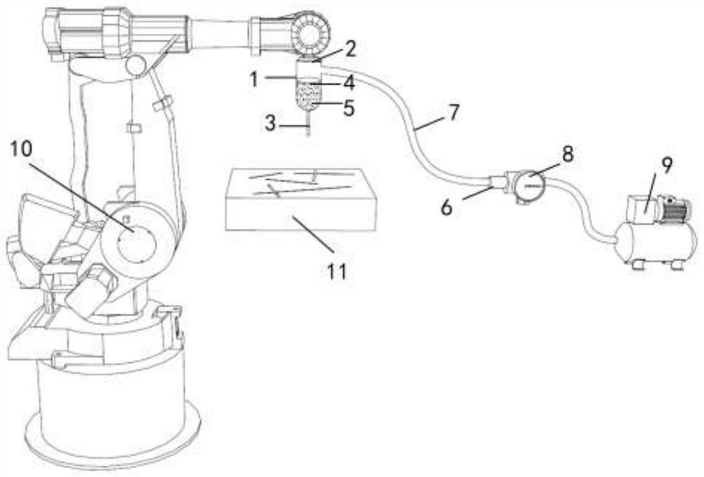
[0030] refer to figure 1 , the present invention provides a cement-based 3D printing rock mass model crack filling device, comprising a mechanical arm 10, a feeding mechanism is installed at one end of the mechanical arm 10, and the feeding mechanism includes a barrel 1 fixed to the mechanical arm 10, the capacity of the barrel 1 It is 300ml, the barrel wall is transparent, the material barrel 1 is provided with a fissure filling material 5, the bottom of the barrel 1 is provided with a fractured rock mass geological model 11, the side of the barrel 1 away from the mechanical arm 10 is fixed and connected with an air supply mechanism, The air supply mechanism includes an air pump 9 in communication with the cartridge 1 .
[0031] In the present invention, by setting the mechanical arm 10 and installing the mechanical arm 10 with the feeding mechanism, the mechanical arm 10 has high geometric precision, accurate positioning and high degree of automation. The amount of crack fi...
Embodiment 2
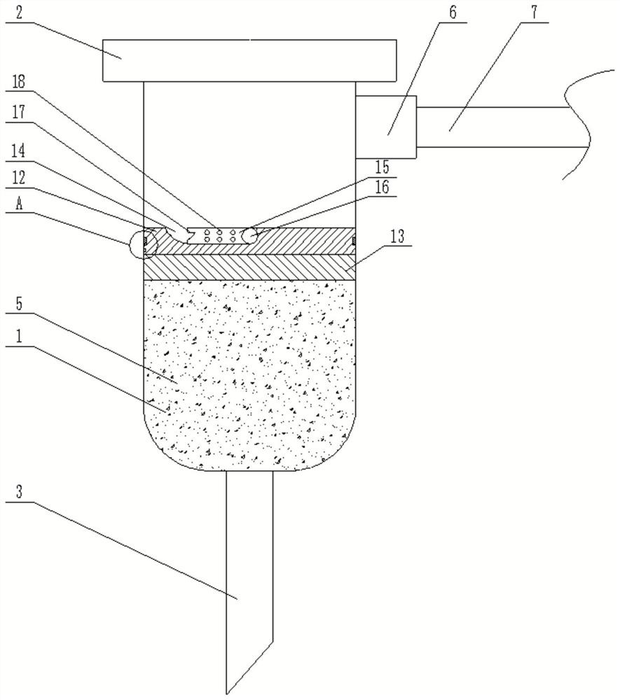
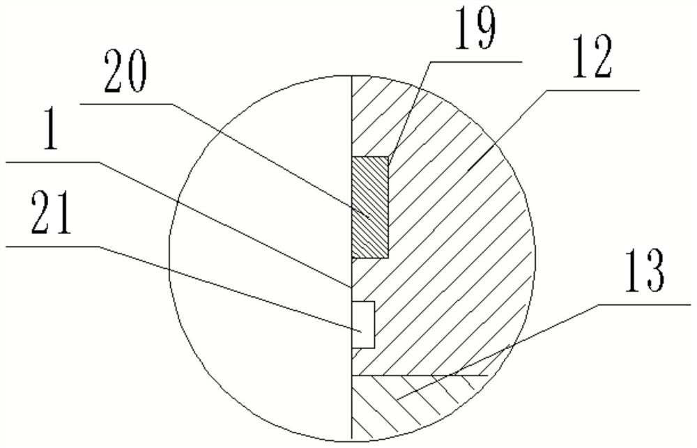
[0051] On the basis of Example 1, refer to Figure 2-3 , the piston 4 includes a connecting seat 12 slidably connected in the barrel 1, the bottom of the connecting seat 12 is fixed with a connecting pad 13, the connecting pad 13 is in contact with the crack filling material, and the top surface of the connecting seat 12 is provided with a first groove 14. One end of the first groove 14 is rotatably connected with a rotating handle 15, one end of the first groove 14 is installed with a movable shaft 16, the movable shaft 16 is hinged with a rotating handle 15, and the first groove 14 is away from the movable shaft 16. One end is provided with an arc surface, the end of the rotating handle 15 away from the movable shaft 16 is provided with a second groove 17 , and the outer wall of the rotating handle 15 is provided with a plurality of third grooves 18 .
[0052] When it is necessary to add the fissure filling material 5 in the barrel 1, the piston 4 needs to be taken out, firs...
Embodiment 3
[0057] On the basis of Example 1 and Example 2, refer to Figure 4 , one end of the airtight bayonet connector 6 is fixedly connected with the conduit 7 through the connecting mechanism, and the other end of the airtight bayonet connector 6 is provided with a threaded interface, through which the airtight bayonet connector 6 is connected to the barrel 1 and the air pressure respectively The valve 8 is fixed and communicated.
[0058] The connecting mechanism includes a first chute 22 symmetrically arranged in the inner wall of one end of the closed bayonet connector 6 close to the conduit 7, the first chute 22 is slidably connected with a limit block 23, and the limit block 23 is located in the first chute 22. One end is fixedly connected with a spring 24 which is fixedly connected with the inner wall of the airtight bayonet connector 6 .
[0059] A sixth groove 26 is provided at the port of the conduit 7 that is close to the airtight bayonet connector 6 . The sixth groove 26...
PUM
 Abstract
Description
Claims
Application Information
 - R&D
- Intellectual Property
- Life Sciences
- Materials
- Tech Scout
- Unparalleled Data Quality
- Higher Quality Content
- 60% Fewer Hallucinations
Browse by: Latest US Patents, China's latest patents, Technical Efficacy Thesaurus, Application Domain, Technology Topic, Popular Technical Reports.
© 2025 PatSnap. All rights reserved.Legal|Privacy policy|Modern Slavery Act Transparency Statement|Sitemap|About US| Contact US: help@patsnap.com


